

© Wonders of World Engineering 2014-


Part 47
Part 47 of Wonders of World Engineering was published on Tuesday 18th January 1938, price 7d.
Part 47 includes a photogravure supplement showing modern electrical auxiliary equipment. This section illustrates the article on Electrical Auxiliaries.
The Cover
The cover this week shows a mercury arc rectifier which has been installed in the new office buildings of the London Midland and Scottish Railway at Euston, London. The rectifier converts the electrical supply from alternating to direct current to give a steady light without trace of flicker. The operation of mercury arc rectifiers is described this week in the chapter entitled “Electrical Auxiliaries”.

Contents of Part 47
In a Canadian Gold Mine (Part 2)
Grass Drying Equipment
Electrical Auxiliaries
Electrical Auxiliaries (photogravure supplement)
Sir Charles Parsons, 1854-1931
Calculating Machines
An African Power Scheme (Part 1)
In a Canadian Gold Mine (Part 2)
This chapter, by Harold Shepstone, describes the Hollinger Gold Mine, Ontario, a great Canadian enterprise which rivals the famous gold mines of South Africa. So rich is the mine that experts have declared that gold probably continues to a depth beyond human reach. Yet it was less than thirty years ago that two prospectors staked their claim to this Canadian El Dorado. The article is concluded from part 46.
(Pages 1329-
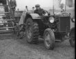
Grass Drying Equipment
Science has found that the food value of young spring grass can be preserved indefinitely by drying, and machinery has been evolved which enables grass to be dried and stored for the winter feeding of livestock. Young spring grass has a high protein value, and that a substance known as carotene is also present in it. This substance is of great value for increasing the milk yield of cows. The science of grass drying consists of drying the grass so that the moisture is driven off without destroying these two valuable constituents. Long and patient research has shown that this goal can be achieved if the correct methods are adopted. This chapter, which describes these methods, is by Rolt Hammond.
(Pages 1331-1335 )
Click on the icon to see a British Pathé newsreel clip on “Drying Grass” (1936) which shows some of the processes described in this chapter.
The Curtis-Hatherop Grass Drying Machine
THE CURTIS-HATHEROP MACHINE is arranged to dry grass in two stages. Wet grass is first placed on a perforated tray, through which hot gases rise from the furnace. In the second stage, the grass is dried in an enclosed tray. There are two pairs of trays, the grass being dried in one pair, while the filling, transferring and emptying processes are taking place in the other pair.
(Page 1333)
Electrical Auxiliaries: Photogravure Supplement - 2
INDICATOR BOARD AND CONTROL DESK in the station from which the distribution of electricity over the entire Central England areas is controlled. The coloured lamps in the large diagram on the wall show whether the various circuit-breakers at the generating stations are in the “open” or “closed” position, and the meters below them enable the engineers to check the load at any particular point in the distribution network. The engineers are in telephonic communication with all the generating stations in the area, and can give instructions to the control engineers at those stations, thus acquainting them instantly with any emergencies, such as sudden overloads, which may necessitate bringing extra stations into action. Between the engineers at the desk is a large illuminated diagram which is more detailed than the schematic diagram on the wall. Manually operated indicators on this diagram are set to keep it constantly up to date and warning signals on the wall continue to flash until these indicators are correctly set.
(Pages 1342-1343 )
Sir Charles Parsons, 1854-1931
 A remarkable intuitive faculty and a firm belief in the value of experiment contributed largely to the success of Sir Charles Algernon Parsons, not only in the adaptation of the turbine principle to generators and marine propulsion, but also in his other scientific activities.
Sir Charles Algernon Parsons, who died in 1931, ranks among the most important men in the
history of engineering. At an early age Parsons concluded that the defect of the reciprocating steam engine was that the motion of the piston had to be converted into a circular motion. He considered that it should be possible to produce this circular motion directly from the energy of the steam without any intermediate stage. This essentially is the principle of the turbine, and in 1885 Parsons produced the world’s first practical steam turbine. This historic machine now rests in the Science Museum, South Kensington. This first machine developed only four kilowatts, but before the inventor died turbines were being made with a power of fifty thousand kilowatts. However, it is no more true to say that Parsons invented the turbine than it would be to say that Watt invented the steam engine; but it was Parsons’s genius that paved the way for the progress which has been made in recent years.
This chapter is by Norman Walley and is the seventeenth article in the series on Makers of Engineering History.
(Pages 1347-1350 )
You can read more on Steam Turbine Construction in part 50, and on steam turbine engines in Shipping Wonders of the World.
Electrical Auxiliaries
Photogravure Supplement - 3
CORE TYPE TRANSFORMER removed from its oil tank. This 75,000-kVA three-phase machine converts 11,000 volts to 70,500 volts. The steel cores are built of sheets of thin sheet stampings, each backed with insulating paper. The coils are generally made of copper strip, bent to shape in sections and welded together.
(Page 1344)
Electrical Auxiliaries
Enormous currents and voltages are involved in modern electrical equipment and exceptionally storng and efficient apparatus, such as switchgear, circuit-breakers , reactors and transformers, must be used to keep these powerful forces in harness. The amazing advance of electrical engineering in the last thirty years is more probably due to the introduction of the turbo-alternator than to anything else. This has increased the output of a single generating plant to upwards of 100,000 kilowatts, operating at voltages as high as 11,000. These enormously increased voltages have given rise to a new problem in heavy electrical engineering, the problem of devising switchgear and other apparatus capable of handling such power forces with safety. This chapter describes the methods adopted in handling such heavy electrical currents.
An excellent example of the immensity of modern switching machinery is the oil circuit-breaker which has superseded the knife switch. The three-phase oil circuit-breaker is the type generally adopted for main switching operations. It comprises three pairs of contacts immersed in a tank containing as much as 500 gallons of special insulating oil. The circuit is closed by a powerful electrical solenoid, which, when energized, lifts three bars simultaneously to connect the three pairs of contacts. The total load on the solenoid may be as much as four tons, for the metal bars are lifted against the pressure of powerful springs and latched in position, so that when the latches are released the springs will throw the contact bars down and break the circuit.
This operation causes a powerful arc. Although the dielectric properties of the oil serve to quench the arc, the intense heat generated causes a certain amount of carbonization - so that frequent purification of the oil is necessary. The stresses that are brought to bear on such a circuit breaker make it necessary for it to be of exceptional strength.
The means adopted for breaking the powerful arcs that are caused by the opening of contacts in switchgear are ingenious to a degree. Reactors and transformers are among the other apparatus for dealing with heavy electrical currents, which are described in this chapter. The chapter, by H M Andrew, is supplemented with a photogravure section.
(Pages 1336-1346 )
37,500-KVA Three-Phase Power Transformer
37,500-KVA THREE-PHASE POWER TRANSFORMER, 6,800 volts to 33,000 volts, installed at Belfast Corporation Power Station. Above the transformer tank is the oil conservator tank through which the transformer “breathes” to prevent entry of moisture or dirt. On the left are the cooling radiators for removing the heat generated in the oil.
(Page 1339)
Electrical Auxiliaries
Photogravure Supplement
FEEDER SECTIONS comprising line isolator with earthing switch, by-pass isolator and oil circuit-breaker at the 132,000 volts double busbar substation at Swanscombe, Kent, in the south-eastern area of the British grid system. The lines on the right of the picture lead up to the pylons of the overhead feeder lines.
(Page 1340)
Pipe Line and Haulage Track
PIPE LINE AND HAULAGE TRACK for the Pangani Falls power scheme during early stages of the work. The pipe line is 1,230 feet long; the first 418 feet have a diameter of 6 ft 6 in; the rest of the line is 6 feet in diameter. There are four main concrete anchorages, tow of which appear in this illustration. They are reinforced with steel, their foundations being carried down to solid rock.
(Page 1356)
The Development Headings of Hollinger Mine
IN THE DEVELOPMENT HEADINGS of Hollinger Mine a mechanically operated scraper, resembling a giant scoop, burrows into the debris left by a blast. A round of about twenty holes having been drilled, explosives are rammed home and fired. Between 30 tons and 50 tons of rock are brought down and hauled out by the scraper. The photograph shows the 1,700 feet level.
(Page 1329)
Calculating Machines
Mathematical calculations which would occupy experts for years can be carried out almost instantaneously by ingenious and complicated machines. Simpler forms of automatic calculators have also been developed, and now they are indispensable adjuncts of modern commerce. In thousands of offices all over the world complicated mathematical transactions are carried out by various forms of calculating machinery. Simply by pressing keys on a keyboard similar to that of a typewriter it is possible to add figures, subtract, multiply or divide them without any risk of error through human fallibility. Inventors for years had been trying to evolve a machine that would carry out the most complicated mathematical functions, but it is only comparatively recently that these amazing machines have reached their present state of perfection. In this chapter, F E Dean describes the invention and the development of various kinds of calculating machinery. This is the seventh article in the series Invention and Development.
(Pages 1351-1355 )


Mercury Arc Rectifier
MERCURY ARC RECTIFIER used for converting alternating into direct current. The rectifiers are built up in metal containers, fitted with a complete water-cooling system for the anodes and pumps for continuous evacuation. As the metal shells are “alive”, they are mounted on insulators and the whole unit is guarded by railings.
(Page 1336)


An African Power Scheme (Part 1)
A hydro-electric station in the centre of the jungle supplies power to several factories near the Pangani River Falls in Tanganyika. The unusual difficulties which have been overcome have made this one of the most interesting water-power schemes in the world. This chapter by Howard Barry, and is the seventh article in the series Wonders of Water Power. The article is concluded in part 48.
(Page 1356)
Electric Calculator
ELECTRIC CALCULATOR which records individual totals and grand accumulative totals. Individual totals are recorded after each operation, in the front dials. Depression of the bar on the right transfers the result and adds it to the total in the top dials. This model can be made to subtract by touching the minus key on the right.
(Page 1353)


Automatic Book-Keeping Machine
AUTOMATIC BOOK-KEEPING MACHINE which prints statements and posts ledgers and journals in one operation. There are no type-written descriptions, but various keys print such abbreviations as GDS for “Goods” and B/FD for “brought forward”.
(Page 1353)
