THE task of building a bridge or viaduct across a waterway frequented by small craft only is generally much easier for the engineer than when the waterway is used by large ships. In such conditions, to provide headroom for ships with a fixed deck bridge when the banks of the waterway are low is almost always out of the question. For one thing it would involve long and costly approaches to reach the desired height. With a low approach, then, some other method has to be adopted. The bascule bridge and the transporter bridge, described in the chapter “Transporter Bridges”, are two types of bridge suitable for the purpose, although they have their limitations.
Examples of two other types are here shown. The upper illustration shows one of the eleven vertical lift bridges across the Welland Ship Canal, in Canada. As its name implies, the deck of this bridge is lifted bodily up out of the way when a vessel has to pass. This particular bridge is situated at the city of Welland and has a 30-feet roadway. When closed the deck is only 15 feet above the water level, but when it is open it is about 111 feet above the water level. There is a clear channel 200 feet wide to be spanned and the length of the bridge, measured between the bearings, is over 231 feet. The deck is suspended at the ends by wire ropes passing over large pulleys at the top of the guiding towers, counterweights inside the towers being attached to the other ends of the ropes.
The total weight of the lifting span and counterweights is 2,300 tons. The operating machinery is carried in a cabin situated centrally on the lifting span. Winches pay out and take in wire ropes and are driven by electric motors. The current for these is picked up by a shoe travelling on conductor wires stretched vertically down the front of the towers. A petrol engine is fitted for use in the event of current failure.
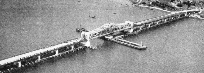
The bridge shown in the lower illustration is of an older type, although it was completed in 1936. A span in the deepest part of the waterway is pivoted on a vertical axis so that it can be swung round to a position at right angles to the roadway and so leave a clear passage for ships at either side.
The bridge shown crosses the River Forth at Kincardine, Scotland, and its total length, with its approach spans, is over half a mile. The swing span is 364 feet long and when it is open there are two navigational openings each 150 feet in width; when closed there is a clear headroom of 30 feet, at high water. The weight of the swing span is 1,600 tons and is taken on sixty rollers arranged in a circular path. The control cabin is at the centre of the swing span and the operating machinery is situated in the central pier. The machinery consists of two 50 horse-power motors, driven by a 160 horse-power oil engine. Photoelectric cells, the operation of which is described on page 390, indicate when the swing span is in correct alignment with the approach roads. The roadway is 30 feet wide.


 THE task of building a bridge or viaduct across a waterway frequented by small craft only is generally much easier for the engineer than when the waterway is used by large ships. In such conditions, to provide headroom for ships with a fixed deck bridge when the banks of the waterway are low is almost always out of the question. For one thing it would involve long and costly approaches to reach the desired height. With a low approach, then, some other method has to be adopted. The bascule bridge and the transporter bridge, described in the chapter “Transporter Bridges”, are two types of bridge suitable for the purpose, although they have their limitations.