The first practicable microphones appeared in 1878, but it was the invention of radio transmission which did most to stimulate the research that has evolved the amazing instruments so extensively used to-day
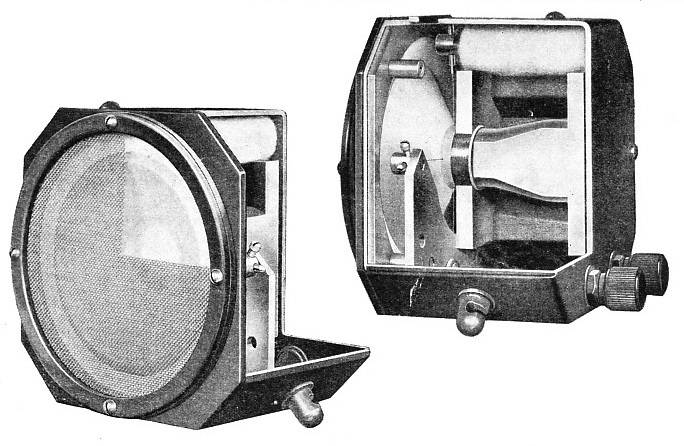
MOVING-COIL MICROPHONES are shown in partial section in these two photographs. The fundamental principle of the moving-coil microphone is that the movement of any conductor in a magnetic field causes corresponding voltages to be set up in that conductor. A diaphragm carries an extremely light coil of wire which has a slight clearance between the poles of a permanent magnet. Sounds near the diaphragm cause air waves to strike it, and to move the coil at corresponding frequencies. The voltages thus set up in the coil vary in proportion to the strength of the air wave.
THE force exerted by the ordinary house fly as it pushes off in preparation for flight is probably in the region of one dyne, yet the ear can detect a medium-pitched note when it impinges on the drum with a pressure of only one five-thousandth part of a dyne. As a dyne is a unit of force equivalent to only of the weight of a pound, these two minute quantities provide a striking testimony to the sensitivity of the ear and emphasize the fine limits to which the electrical engineer is accustomed to work.
In the lighter branches of electrical work, particularly in radio communication, the engineer is undoubtedly dealing with higher speeds and more delicate effects than in any other branch of applied science. The modern microphone must faithfully respond to sound variations which exceed 10,000 vibrations a second and which may also vary in magnitude by as much as four million to one.
The microphone is considerably older than radiotelephony. The earliest attempt to convert sound vibrations into corresponding electrical impulses was successfully made by Graham Bell, the inventor of the telephone. In this attempt he made use of the principle that changes in magnetic flux will be accompanied by the generation of proportional voltages. A diaphragm of ferrous material was arranged close to the pole of an electro-magnet so that, when the diaphragm moved under the influence of sound waves, voltages were set up in the magnet coil. If these electrical impulses are transmitted along a wire, the original sounds can be reproduced at some remote point by reversing the process. In this arrangement we have the basic features of the telephone, although the signals generated in the manner outlined would be so weak as to be inaudible at a distance.
The year 1878 saw the first practicable microphones. In America Edison patented his carbon transmitter; in England Professor Hughes published the results of his research into the subject. Hughes reached the important conclusion that any loose contact between conductors would act as a telephone transmitter. He made a number of demonstrations of the practical application of these discoveries, using such simple equipment as three ordinary nails for a microphone. Two nails were laid side by side with their heads at opposite ends and the third nail was laid across these at right angles. A low voltage was applied to the heads of the two parallel nails and a telephone receiver connected in series. The loose contact afforded by the nails provided a means of sound -detection so sensitive that the walking of a fly could plainly be heard. Hughes later made use of a carbon pencil sharpened at both ends and set in two carbon blocks, the whole then being mounted on a deal sounding board. A battery and receiver were connected in series and a relatively efficient microphone circuit resulted.
SECTIONAL VIEW of a carbon microphone of good quality. Carbon microphones were first produced in 1878 by Edison, in America, and by Professor Hughes, in England. The principle discovered was that any suitable loose contact between conductors of an electric current would act as a telephone transmitter. Later Professor Hughes set a carbon pencil, sharpened at both ends, in two carbon blocks mounted on a deal sounding board. When a battery and receiver were connected in series a microphone circuit of remarkable efficiency for such simple apparatus was formed.
The next step forward followed within a few months; this was represented by the carbon granule microphone, which is still in wide use to-day. In this instrument a box-shaped container is closely packed with particles of carbon and a thin membrane or diaphragm is stretched across the open end of the box. Current is passed continuously through the carbon by means of a battery, but it can be made to vary considerably in value when sound waves impinge on the membrane. This variation is due to the compression of the carbon granules when the diaphragm moves, this, in turn, causing the resistance of the carbon to the flow of current to decrease. For sensitivity, a carbon granule microphone is highly efficient, and until the beginning of the twentieth century its limitations in other directions were not felt. Its sole application up to that time was to the crude, forms of telephony then existing.
With the advent of radiotelephony, it became necessary to use much higher power. This introduced a number of serious problems, because no means of amplifying small currents were available until the development of the thermionic valve by Fleming and de Forest many years later. This development is referred to in the chapter “International Exchange”.
At first the radio pioneers attempted the obvious method of passing much heavier currents through the microphone itself. These efforts proved abortive, as the instruments then suffered from intolerable heating. Cooling by air, water and oil were all tried in turn by various investigators. One water-cooled design successfully passed a current of 15 amperes, which is approximately 150 times the amount that can be carried by a non-cooled type. Despite these improvements and other ingenious attempts, such as connecting several instruments in parallel, the carbon microphone was not suitable for the tasks to which it was being applied. Investigation then turned to other possible means of converting sound waves into corresponding electrical impulses. The discovery that sound waves impinging on a jet of liquid caused the volume of the jet to vary in proportion gave rise to the hydraulic or liquid microphone. Majorana’s design incorporated such a jet spurting on to a metal disk, which was surrounded by, but insulated from, a concentric metal ring.
STUDIO NUMBER ONE at the Maida Vale, London, Studios of the British Broadcasting Corporation. The demand ror hign quality m radio broadcasting led to continual improvements in the means for the translation of sound into electrical energy. Large studio microphones are mounted on trolleys for ease of handling, and are connected by trailing leads to points in the studio walls.
Conduction between disk and ring took place through the flow of liquid over the two. When the liquid increased in volume (governed by the intensity of the sound waves) the path between the two became more conductive.
In this way a serviceable microphone was produced and in later types of hydraulic instruments as much as 500 watts could easily be handled. So successful were some liquid microphones that the type persisted for several years after the introduction of valve amplifiers.
Debt to Broadcasting
A great many important developments were held up by the lack of amplifying facilities. During the first years of the twentieth century several inventors were working on condenser microphones, similar in principle to the latest types, when they were impracticable because of their low power capacity.
Radio broadcasting must take the major credit for stimulating the design and production of effective and reliable microphones. The wonder with which the reception of speech and music was justifiably acclaimed at first made the inefficient reproduction unnoticeable.
The B.B.C. in Great Britain at first used carbon instruments, which were later replaced by a form of moving-coil microphone. Still later a reversion was made to carbon in the form of the highly improved Marconi-Reisz design. A non-linear characteristic and a tendency to background noise were the main defects in the design, which differed from the ordinary carbon instrument in features of construction, not in principle. The granules were contained in a large shallow area, instead of a fairly deep container. A thin sheet of mica replaced the usual diaphragm and the granules were of varying size so that the spaces between the larger granules would be filled in by the smaller; this yielded sensitive and consistent performance.
There are few examples found in Nature of substances which have the extraordinary property of converting mechanical energy direct into electrical energy. The phenomenon is known as the piezo-electric effect (which means pressure electricity). It was known as early as 1780, when M. Coulomb discovered that certain substances, when subjected to pressure, exhibited an electric charge on opposite faces. Many eminent scientists, including the Curies of radium fame, later investigated the effect.
The Curies showed that, according to the law of the conservation of energy, the converse of the phenomenon must also be true. They demonstrated, therefore, that the application of an electric field to piezo-electric substances caused mechanical deformation. In present-day radio engineering practice the effect is widely exploited. It is used to control the frequency of a complete transmitting station within close limits, and is also adopted for microphones, loudspeakers and gramophone pick-ups.
Quartz, tourmaline and Rochelle salt crystals are prominent natural examples of substances having piezoelectric properties. A good quartz crystal is perfectly hexagonal in shape and pointed at either end. Pressure cannot be applied anywhere to produce corresponding electric charges. If the points of the crystal are pressed, for example, there will be no effect. The crystal is sensitive only at the corners of the hexagon and on the flat faces. The polarity of the charges generated changes according to whether the crystal is in tension or in compression.
For modern microphones and loudspeakers the crystals (Rochelle salt) are grown artificially. Each main crystal is about 22 in. long, 31 in. wide and 2 in. thick, and weighs about 5 lb. From this raw material, a larger number of crystals is carefully cut for acoustic work. The dimensions of the cut crystal govern its natural frequency so that it is of extreme importance that cutting should be carried out with perfect accuracy.
The method of making use of the piezo-electric effect in practical microphone design is to allow the sound waves to impinge on the prepared crystal surface. These waves exert a mechanical force, thus causing proportional voltages to be set up on the faces of the crystal. In one type two thin crystals are mounted in a rectangular insulated frame so as to form a hollow box of which the two main sides are the crystals. Silver connecting wires are taken from the crystals to the exterior, whence they may be joined up to an amplifier. The construction of the instrument is such that when sound waves reach the microphone, both crystals generate voltages which are additive. Should the instrument be subjected to mechanical shock, however, each crystal will again generate a voltage, but of opposite phase, thus tending to cancel out. The dimensions of the crystals used are a little over | in. square by in. thick. Numbers of these little “sound cells” are connected together and built in one unit to form the usual type of commercial crystal microphone.
THE CRYSTAL MICROPHONE makes use of what is known as the piezoelectric effect. Sound waves impinging on the surface of Rochelle salt crystals exert a mechanical force and set up a voltage on the crystal faces. Silver wires transmit this voltage to an amplifier.
Movement of any conductor in a magnetic field causes a voltage to be set up in that conductor. The moving coil microphone is a direct application of this fundamental principle. A diaphragm carries an extremely light coil of wire which has a slight clearance between the poles of a permanent magnet. Speech, music or other sounds in the vicinity of the diaphragm cause air-pressure waves to strike it, and in so doing give rise to a movement of the coil. In this way voltages are set up in the coil which are directly proportional to the air waves which caused them. After amplification they are suitable for actuating a loudspeaker.
Apart from the simple question of loudness, one note is distinguishable from another only by its pitch or by the number of air vibrations a second it represents. As the coil moves in synchronism with the frequency of the note reaching the diaphragm, the output of an instrument of this type depends upon the velocity of the coil. The voltage set up in the coil, however, is dependent upon its velocity also, and careful design is necessary to ensure that this shall be strictly proportional to the pressure of the sound waves at all frequencies. Good commercial instruments can be produced having a uniform response of from 10 to 10,000 cycles a second.
Another type of instrument, known as the velocity microphone, is basically similar to the moving coil in principle. A permanent magnet is used, but the coil is replaced by a thin corrugated strip or ribbon of aluminium, measuring less than one ten-thousandth of an inch in thickness. No diaphragm is necessary with this type, the sound waves impinging direct on to the ribbon. For all practical purposes the mass and inertia of the thin foil are negligible, and it will therefore take up the motion of the air particles reaching it. This movement, the ribbon being subject to a transverse magnetic field, gives rise to induced voltages which are led off by suitable connexions to an amplifier.
Outside the Audible Range
More than fifty years ago an electrostatic telephone was invented. It relied for its operation on the variation of capacity between one fixed and one moving plate. The arrangement was essentially a two-plate condenser, one plate being the diaphragm, so that sound waves caused the distance between the plates to alter and, therefore, varied the capacity accordingly. In the first decade of the twentieth century experiments were conducted on these lines in a successful effort to produce a condenser microphone.
The diaphragm is placed close to the backplate, the distance between the two being about 1/1000 in. The thickness of the diaphragm is about the same, and it is made of aluminium alloy. By stretching the aluminium tightly, its resonant frequency can be made to lie outside the audible range, and internal resonances caused by the air trapped between the two plates can be compensated for in the design. A potential of about 300 volts is applied to the plates and a resistance is connected in series. It is across this resistance that the alternating signal voltages are developed for subsequent amplification. The condenser microphone has many merits.
One of the oldest microphones — the carbon type — is still the most sensitive, and where requirements as to frequency response and freedom from background noise are not unduly severe, it is undoubtedly the best. It is widely used for telephone sets, aids for the deaf and so on.
Radio broadcasting, telephony, public address equipment and sound films probably comprise the principal applications of the microphone. Its use extends, however, into many branches of industry, and it is also of leading importance in the success of various scientific instruments. Warships incorporate equipment which makes use of the microphone for the detection and location of submarines. Similarly, it is used in certain types of apparatus for detecting the approach of aircraft.
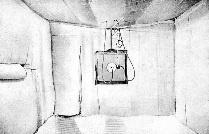
THE TESTING OF MICROPHONES and of loudspeakers is carried out in a room which has been made acoustically dead by the placing of padding over the reflecting surfaces. Thus there is no reverberation, echo or reflection of sound waves which would nullify accurate results.


 he year 1878 saw the first practicable microphones. In America Edison patented his carbon transmitter; in England Professor Hughes published the results of his research into the subject. Hughes reached the important conclusion that any loose contact between conductors would act as a telephone transmitter. He made a number of demonstrations of the practical application of these discoveries, using such simple equipment as three ordinary nails for a microphone. Two nails were laid side by side with their heads at opposite ends and the third nail was laid across these at right angles. A low voltage was applied to the heads of the two parallel nails and a telephone receiver connected in series. The loose contact afforded by the nails provided a means of sound -