

© Wonders of World Engineering 2014-


Part 26
Part 26 of Wonders of World Engineering was published on Tuesday 24th August 1937, price 7d. It was the final part to Volume 1.
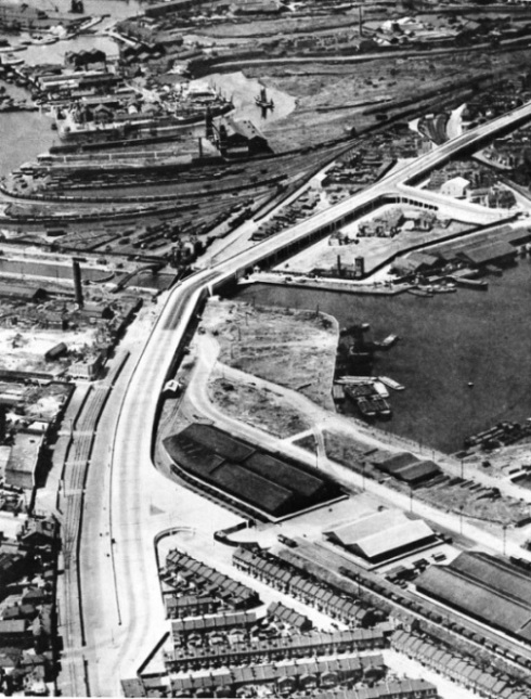
Part 26 includes a photogravure supplement showing the construction of Silvertown Way, which illustrates the article London’s Dockland Highway.
The Cover
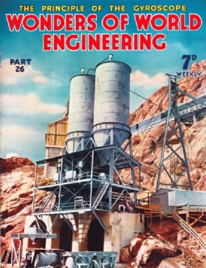
The cover of this week’s part gives some idea of what is required when a big concrete structure is to be built, for it shows one of the several concrete mixing plants used in the building of the Boulder Dam. Altogether, including subsidiary works, about 4,000,000 cubic yards of concrete were required. This amount involved the consumption of 755,360 tons of cement. An unusual feature was the method of charging the containers of the mixing plants from the silos in which the cement was blended and stored. The transport was effected by forcing the cement through pipes by means of compressed air. In one instance the pipe was 5,600 feet long (over a mile), and the cement was delivered to the container at the rate of 76 tons an hour. The cover was issued as a colour plate in Part 38.
Contents of Part 26
Prospecting from the Air (Part 2)
An account of how aerial surveys are carried out in specially equipped machines, with particular reference to the value of aircraft to mining engineers. The article is concluded from part 25.
Making Radio Receivers
Ingenious and elaborate machinery is used for the production in large quantities of radio receivers. The high degree of precision necessary in this work is achieved by the use of special tools and the most modern methods of assembly. To deal with such a large industry in which an enormous number of different types of radio set is produced it is necessary for the sake of clarity to take one representative as an example of the processes in the industry as a whole. This chapter describes the processes that are in operation in one such factory. It is the eighth article in the series on the Romance of Industry.
London’s Dockland Highway
One of the greatest feats of highway engineering that London has ever seen was the building of Silvertown Way, a mile-long stretch of elevated highway which carries heavy traffic for the docks over minor roads, railways and other obstructions. The building of this great highway is described in this chapter. The route which commercial traffic laden with the goods handled by the world’s largest port had to take consisted of narrow, twisting streets hampered by a swing bridge, by level crossings and by right-angled turns. The congestion was appalling. Silvertown Way, an entirely new thoroughfare including viaducts, bridges and approach roads, was opened in September 1934 at a cost of about £2,500,000.
London’s Dockland Highway (photogravure supplement)
London’s Dockland Highway
Photogravure Supplement - 3
SILVERTOWN WAY COMPLETED. The new bridge across the entrance to the Tidal Basin has a span of 103 feet. Two spur roads lead down to the docks from the viaduct which runs about 25 feet above ground level.
London’s Dockland Highway
Photogravure Supplement - 2
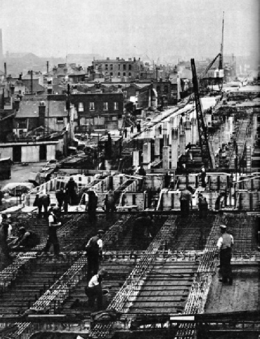
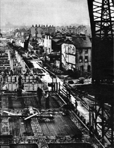
THE MAIN VIADUCT which carries Silvertown Way is of concrete, heavily reinforced with steel rods up to 1½ in thick. The roadway is carried on a concrete deck 1 foot thick, resting on transverse and longitudinal beams supported on rows of six columns rising from pile caps.
London’s Dockland Highway
Photogravure Supplement
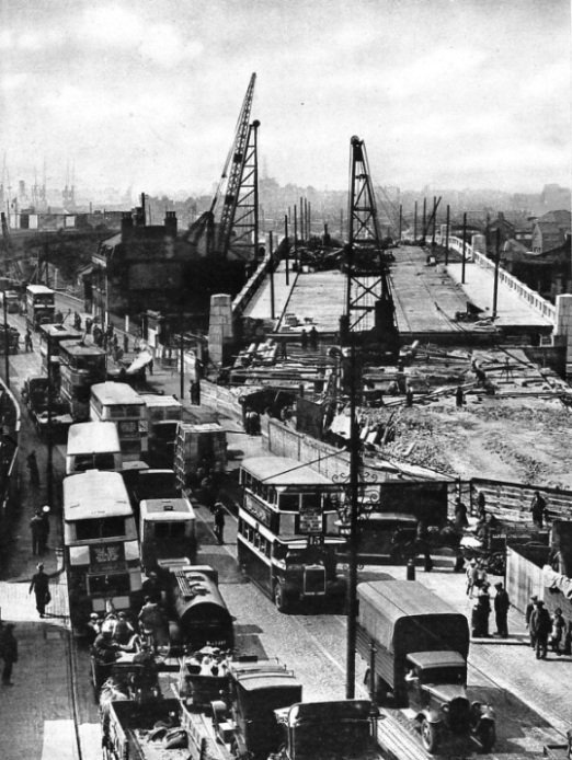
TRAFFIC CONGESTION on Barking Road was enormous before the new bridge was built across the River Lea. The approach to the new bridge can be seen in this photograph. For the foundations of the road large numbers of 14-in piles up to 50 feet long were driven through the subsoil into the firm clay.
Contents of Part 26 (continued)
Machine Tool Development
The enormous steel lathes which are seen in engineering shops to-day are the outcome of Henry Maudslay’s invention of the screwcutting lathe. Even the huge modern boring and drilling machines can be related to this epoch-making invention. The development of machine tools is the subject of this chapter. The machines which are used in workshops to-day for boring, drilling and turning operations are of enormous weight and size, capable of handling work of great dimensions.
Building a Modern Bathing Pool
The design and construction of a large bathing pool, with covered promenades, diving stages, sunbathing decks and a restaurant, is a considerable feat of engineering and one which gives great scope to the worker in reinforced concrete. The accompanying illustrations show several aspects of the building of the municipal bathing pool at Hastings, Sussex, which is one of the largest and most up-to-date pools in Great Britain.
Portable Mechanical Hammer
These machines, which may be likened to gigantic nutcrackers, bear no resemblance to a hammer; but American engineering has produced a machine which almost exactly reproduces, on a greatly enlarged scale, the road-mender’s hammer. A machine of this type is described in this article. It is not used, however, for preparing road metal, but for breaking up rocks and boulders into pieces which can be readily removed. This is the sixteenth article in the series on Modern Engineering Practice.
Principle of the Gyroscope
Aircraft, warships and merchant vessels have derived the most striking benefits from the application of the gyroscope to various instruments, but the gyroscopic principle is involved in many fields of engineering. The principle of the gyroscope - a principle so well illustrated by the toy gyroscopes which fascinate grown-ups as much as they do children - is used in many forms by engineers. The meaning of the properties of the gyro wheel is explained in this chapter which describes how the gyro is put to various uses by the engineer.
END OF VOLUME 1