

© Wonders of World Engineering 2014-


MODERN ENGINEERING PRACTICE - 19
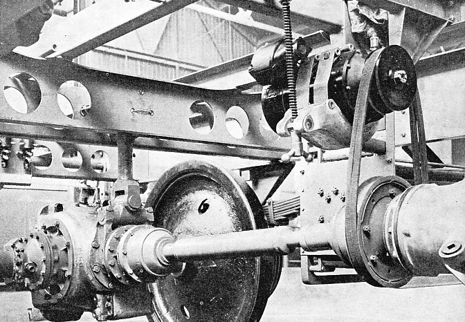
As the steam locomotive goes flashing by it flaunts its coupling rods, and also its connecting rods, if it has outside cylinders. The axles are driven by these long shining rods, but in the motor railcar there is nothing to indicate what drives the wheels. The photograph here reproduced shows the driving axle of one of the latest LMS railcars.
This coach, which carries forty passengers, is capable of travelling at fifty-six miles an hour when required and can accelerate so rapidly that fifty miles an hour can be attained in forty-nine seconds from starting. Inside the coach there is no sign of an engine. At either end a glass partition cuts off a corner for the driver. All that there is to be seen is a pedestal decorated with a few push-buttons and knobs and a hand-brake lever. The longitudinal members of the main frame on which the bodywork rests are seen towards the top of the illustration. At the bottom is the driving axle, of which only one wheel is visible. The coach has four wheels, but only one axle is driven.
The engine is not in the picture, but it is suspended below the frame on the right and is a six-cylinder compression-ignition engine running on heavy oil and capable of developing 130 horse-power. In the same way as a motor-car engine it runs only in one direction and at an approximately constant speed, so that speed changes and reversal have to be effected by means external to the engine. Speed change is done not by gears, as in a motor car, but by what is known as a hydraulic torque converter. A small portion of the converter is seen at the extreme right. Briefly, it amounts to a combination of a centrifugal pump driven by the engine and a turbine on the propeller shaft, the one driving the other by means of an oil stream. The amount of oil circulated can be altered at will so that the speed of the propeller shaft can be varied relatively to that of the engine. The belt seen on the converter coupling drives a dynamo which charges storage batteries having a capacity of 200 ampere hours at 24 volts. The batteries supply current for lighting, for the various magnetic controls and to the starting motor.
The gearbox on the axle at the left is the reversing gear. The propeller shaft ends in a bevel pinion which meshes with two bevel wheels running loose on a shaft. A sliding clutch-pinion is made, by means of an oil cylinder, to engage with one or other of the loose wheels and, according to which is engaged the axle is driven to give a forward or reverse movement to the car. Brakes, actuated by servomotors, are fitted to all four wheels.
You can read more on “Story of the Diesel Engine”, “Tramway Cars and Trolley Buses” and “The Turbine Locomotive” on this website.
You can read more on British Diesel Rail Coaches and Coaches for Road or Rail in Railway Wonders of the World


