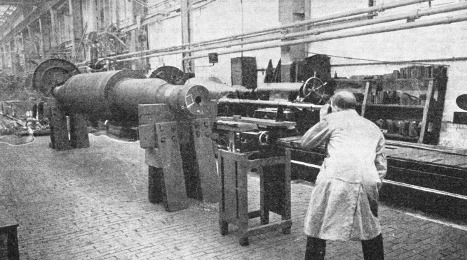
WITH one exception our previous examples of engineering practice have been concerned with what engineers produce, but the phrase “engineering practice” covers also the way in which they carry out their work. The photograph reproduced above, which was taken in the Heaton Works of C. A. Parsons and Co, Limited, shows a stage in the construction of a turbine rotor shaft, that is, of the heavy shaft on which are mounted the blade-carrying disks.
These shafts, which have to spin round at high speeds, are subject to heavy stresses when working, and at every stage of their manufacture have to be minutely examined and subjected to numerous tests. The forging is first carefully heat-treated to remove any internal stresses set up in the steel during its passage through the press. Next, pieces are cut from it; some to be pulled apart and others bent almost double to determine lf the metal is of the required strength.
Then, when the forging has been turned in the lathe, the surface is gone over with prepared paper and what are called “sulphur-prints” are taken from it. These show up any defects in the structure of the metal and, if any non-metallic inclusions are found, they are carefully removed and the place is afterwards scrutinized through a lens. The outside of the shaft having been found satisfactory, the condition of the metal of the interior has to be investigated.
A hole is bored right through the centre of the shaft by a trepanning tool which removes a cylindrical core. This core also is sulphur-printed and examined. Test pieces are taken from it, not because it is to be used, but to find out if the forging is reasonably uniform all the way through. The task of examining the inside surface of the hole is next carried out with an instrument called a “Borescope”, made by Sir Howard Grubb, Parsons and Company.
A tube about 32 in long and fitted with little rollers, so that it can be easily moved, is inserted in the hole in the shaft. One end of the tube is fitted with a powerful electric lamp, a total-reflection prism and a lens. An inspector examines the magnified image through a telescope, pulling the inner tube by stages along the hole till the whole length, in a strip about ¾ in wide has been scrutinized. The shaft is then turned round on its supports and another strip is examined, the operation being repeated until the whole surface of the hole has been gone
over.
The forging is next subjected to magnetic and electrical tests. In the magnetic test the shaft is turned into a huge magnet by passing a current through coils suitably wound through it. The external surface is then sprayed with kerosene carrying finely-divided iron. If there are any cracks, even if so fine as to be invisible, the powdered iron gathers thickly on the edges of the cracks and defines them.
In the electric test a current is passed through the shaft and the difference of potential along its length is measured. If there is only a small drop in potential the forging may be considered sound. A final test, carried out when the disks are in place, consists of spinning the shaft round by motor at a speed of 20 to 25 per cent above its normal running speed. This test is performed in a strong chamber resembling a bomb-proof shelter, without anyone being present. Measurements and examination are made afterwards.