From the early and comparatively simple types of steam generator such as that invented by Trevithick have developed the enormous boilers of to-day, which vary considerably in principle and which are all-important to the engineer on land and sea
THE GALLOWAY BOILER resembles the Lancashire boiler in certain features, particularly in having two cylindrical furnaces side by side. The furnaces unite in one combustion chamber. The Galloway boiler of which a model is illustrated above is 28 feet long, with a diameter of 7 feet. It is capable of evaporating 6,000 lb. of water an hour.
IN its simplest form, we know the boiler well enough as an ordinary household kettle. Whether there is any real foundation for it or not, the story of James Watt having received inspiration from one of these homely articles is one that will die hard. The modern steam generator, in any one of its many forms, however, is as far removed from a domestic kettle as New York’s Empire State Building or the Stockholm City Hall is from a hut in a Zulu kraal.
In the earliest days of steam engineering the boiler was an extremely simple apparatus. The function of a boiler used in connexion with an eighteenth century Newcomen engine was not to produce high-pressure steam for driving a piston in a cylinder, but merely to fill the cylinder with low-pressure steam. This low-pressure steam was then allowed to condense so that the atmospheric pressure forced down the piston, in the course of filling up the vacuum formed by this condensation.
The boiler on Cugnot’s traction engine, built towards the end of the eighteenth century, at once reminds us of a kettle (see the chapter on “Early Steam Coaches”); but here already there is an important difference. Cugnot arranged for his “kettle” to be internally fired, thereby increasing its efficiency through its heating surface.
Although Cugnot must be given his due for having designed a remote ancestor of the motor car, it must not be forgotten that the internally fired boiler is of great antiquity. It was known to the Romans at least 1,800 years ago. The history of boilers, however, is neither interesting nor important until the early years of the nineteenth century, when Trevithick began to use high-pressure steam for driving his stationary and locomotive engines. There are two great classes of steam boilers to-day. They are the tank boiler and the tubular boiler. Tubular boilers, in their turn, are divided into two “sub-families”, namely, fire tube boilers and water tube boilers. The tank boiler, as its name implies, consists of a shell or tank containing the water for steam raising. It may be either internally or externally fired, the heating agent in the latter instance being applied to the underside of the shell and enclosed in a furnace lined with firebrick. External firing, however, is unusual, and in ordinary tank boilers the fire is contained in a grate enclosed within the shell.
Of the tubular boilers, in the fire tube boiler the hot products of combustion are carried through a number of flue tubes which are surrounded by the water inside the boiler. In the water tube boiler, generally, the process is reversed — the water from which steam is being raised is carried by a series of tubes through the hot gases from the fire, these tubes being in connexion with one or more steam drums. A certain amount of combination may be carried out; for instance, the firebox of a fire tube boiler may contain a series of cross water tubes, designed to increase the heating surface and to assist in the circulation of the water.
Water tube boilers are frequently used for marine work. The classical example of the fire tube class is the loco-type boiler, which is to all intents and purposes universally in use on steam railway locomotives. There have been notable exceptions. The well-known L.N.E.R. locomotive No. 10000 was built with a Yarrow water tube boiler, and the Brotan water-tube boiler has been applied to a number of railway engines in Central European countries. Various applications of firebox water tubes have been made in this direction, too.
The Cornish boiler is a simple example of the tank boiler, consisting of a cylindrical shell with a single central flue. At one end of this flue, which is completely surrounded by water, the grate is situated. The flue tapers slightly towards the other end, whence the products of combustion are drawn off through a brick flue, to be discharged into the chimney. The central flue is attached at either end to the flat end plates of the boiler, but is not otherwise supported.
Corrugated Flues
The Cornish boiler varies considerably in size. A normal maximum size is 25 feet, with a diameter of the shell of 6 ft. 6 in. A typical working pressure is 90 lb. per sq. in., though it is possible to design a Cornish boiler for pressures up to 200 lb. per sq. in. In the top of the shell are the steam delivery pipe, a manhole for cleaning and examination, and one or more safety valves. The valves are a feature of all boilers, and may be spring-loaded or weight-loaded. Sometimes a spring-loaded valve and a weighted valve are both provided. The weighted valve is extremely simple, but it is easily tampered with by having additional weights hung on the lever. The lock-up spring valve is proof against this.
A Cornish boiler, just as any other central flue boiler, may have additional heating surface provided by cross tubes m the flue. A standard Cornish boiler made by one firm is 26 ft. 3 in. long, with a diameter of 6 ft. 2 in. It has a single flue with a diameter of 3 ft. 3 in. at the firing end, and contains four cross tubes. The grate area is some 21 sq. ft. and the total heating surface (flue and water tubes) 550 sq. Ft.
The Lancashire boiler belongs to the same family as the Cornish boiler, and is one of the most popular types for supplying steam to engines in factories in Great Britain. The Lancashire type owes its name to the old firm of Fairbairn (at Manchester), which first introduced this type. The Cornish boiler is so called from its invention by Trevithick and its use in the Cornish tin mines. The Lancashire boiler resembles the Cornish, but is provided with two parallel flues, generally containing cross water tubes.
Care must be taken with all boilers to prevent the water level from falling so low as to cause overheating of the flues. This would cause serious damage to the boiler and might cause an explosion, action on a lever of a float inside boiler can be arranged to lift the safety valve when the float drops below a certain level, irrespective of the pressure at the time, and a warning whistle is sometimes fitted. Additional safeguards in the form of visual signals are provided by the water gauge and the pressure gauge.
Boilers have their weak points under pressure, and in such generators as have been described, these are found at the ends. One way of overcoming the weakness is to adopt a dish form for the boiler ends. With dished ends, at the same time, allowance has to be made for expansion and contraction in their action on the internal flues. The flues may be partly corrugated to allow for this, the corrugated section having a concertina action. A 30-feet Lancashire boiler expands three-quarters of an inch when fired up to produce a pressure of 160 lb. per sq. in. Where flat instead of dished ends are used, they are reinforced by internal stays. Steam may be taken either from the top of the boiler shell or from a dome or steam drum mounted on the top. A dome is generally considered, to make a boiler more proof against priming — that is, the carriage of water into the steam pipe — than a domeless boiler.
MODEL OF AN EARLY WATER TUBE BOILER designed by Sir Goldsworthy Gurney in 1825 for his steam carriage. The boiler was made of wrought-iron pipes bent to the shape of a hairpin. The ends were held in cast-iron horizontal headers joined by downcomers. To aid circulation of the gases, brick baffles were inserted in the grate formed by the lower legs of the pipes.
In part the Galloway boiler closely resembles the Lancashire boiler. It has the same shape and has the same two cylindrical furnaces side by side. These furnaces, however, deliver the products of combustion into a single large flue running the rest of the length of the boiler. This flue is kidney-shaped in section, with the concave curve downwards. It contains a relatively large number of cross water tubes. The Galloway tube is conical, with its wider opening upwards. This causes an easy and rapid circulation of the water. In all the foregoing tank boilers the products of combustion, having left the internal flues, generally pass along the sides of the boiler, inside the brick casing, and then downwards and underneath it before being admitted to the chimney. A Galloway boiler 30 feet long and 9 feet in diameter, with twenty-five conical water tubes in the flues and having 1,310 sq. ft. of heating surface and a grate area of 43 sq. ft., will weigh ordinarily about thirty-one tons.
The compound Cornish boiler is a cross between the ordinary tank boiler and the tubular type. It resembles the ordinary Cornish except that the single central flue extends for only part of the way through the water beyond the. end of the grate, thus forming a cylindrical combustion chamber. At that point it ends in a flat tube-plate, whence a large number of flue tubes carry the firebox gases to the end of the boiler.
Vertical boilers are also of several varieties. The simplest form of vertical boiler is generally bottle-shaped, with the chimney emerging from the middle of the top plate. The top may be flat, conical or dished. At the bottom is the firebox, surrounded by water at the top and sides, with an ash pan underneath it. From the top of the firebox, in the simplest designs, a flue tube runs up vertically through the water and steam space, its extension forming the chimney. The heating surface of this simple boiler may be increased by the addition of cross water tubes — a few big ones or a great number of smaller diameter. Or, again, Field tubes may be provided, these leading the water down vertically and returning it to the crown of the firebox, there being one tube inside another.
In the vertical multitubular boiler, the central flue is replaced by a large number of flue tubes connecting the top of the firebox, which thus forms one tube-plate, with the top of the boiler, forming the other. They discharge into a smokebox, generally conical, on the top of the boiler, the cone tapering to the base of the chimney.
Vertical boilers of these types are not of large size. Their use was formerly much more widespread than it is now. In the days gone by they could be seen supplying steam to small engines for a variety of purposes now served by oil-driven and internal combustion engines. They are still, however, quite common, and may be observed on almost any steam crane, or supplying steam to a donkey engine.
SECTION THROUGH A MARINE BOILER of the Babcock and Wilcox water tube type which for certain conditions is fitted with a water-cooled furnace and a mechanical stoker. The boiler proper consists of a series of inclined parallel water tubes connected by headers at either end which are coupled to a horizontal steam and water drum.
An interesting vertical steam generator is the Cochran boiler. This has a hemispherical furnace, the convex part forming the crown, the grate being arranged inside it at the bottom. This hemispherical shape gives tremendous strength to the furnace in the very place, the crown, where many fireboxes have their weak spot. Further, the crown is a long way below the surface of the water, so that it is unlikely to become uncovered by water and thus get overheated. With a falling water level the flue tubes, which are easily replaced, would be the first parts to suffer because of their peculiar arrangement—for the tubes are horizontal, and above the top of the furnace throughout. This sounds paradoxical in a vertical boiler with the furnace at the bottom, and its explanation is interesting.
In a Cochran boiler there is a vertical combustion chamber above the furnace and opening into one side of the hemisphere. The combustion chamber is lined on its outer side with firebrick, the rest being surrounded, top, side and bottom, by water. From it the flue tubes cross transversely through the water to a smokebox on the other side of the boiler, from the top of which the chimney rises. The steam space in the top of the boiler is also hemispherical, rising in a great dome, the bottom of which has the same diameter as the water space. Because of its shape the steam space is enclosed by a shell of great strength, eliminating the necessity for placing stays within it and therefore making the interior of the boiler easy of access for inspection through the usual manhole.
Where Space is Restricted
The Cochran boiler is a generator of considerable capacity, which at the same time occupies extraordinarily little space. It needs no massive masonry casing and foundation, as do the Cornish and similar boilers. A flat, hard surface for it to rest on is all that is necessary. Cleaning the flue tubes is easy, because of the unhindered access through the smokebox. The large volume of water contained in the boiler gives it a good capacity for heat storage. Cochran boilers may be as small as 3 feet in diameter and 6 ft. 9 in. High. containing 60 sq. ft. of heating surface — or as large as 8 ft. 6 in. in diameter and 17 feet high, with 1,000 sq. ft. of heating surface.
There are variations on the Cochran type. The Cradley boiler has the same shape, with the same arrangement of flue tubes and the same hemispherical firebox. In this boiler, however, the combustion chamber is cylindrical and completely surrounded by water. The smokebox, which is slightly recessed in the Cochran boiler, is entirely outside the shell of the Cradley boiler. Boilers of the vertical type are largely used on board ship for auxiliary purposes. There are also numerous other kinds of vertical boilers.
Of the horizontal fire tube boilers, the loco-type boiler is familiar because of its universal application on railway locomotives, from which it receives its name. Its use is not, however, confined to the railway engine, for it forms a useful steam generator ’ for stationary machinery in places where height is limited. There is little enough room on the frames of a locomotive, where, in addition to considerations of loading gauge (restrictions on account of the width and height of tunnels, and the proximity of trackside buildings) there are those imposed by limited axle loads. The loco-type boiler is also a familiar feature on steam tractors and many road rollers. It was, before the invention of the water tube boiler, a favourite type in torpedo boats, shallow-draught steamers and so forth.
THE LARGE DOME forming the steam space of a Cochran vertical boiler. Through the water, below, the flue tubes cross transversely to the smokebox and chimney from the combustion chamber at the back. The furnace is hemispherical, the grate being arranged inside the convex part at the bottom.
Limitations of size are not the only ones imposed upon the loco-type boiler when it is used for its original purpose. A high chimney is impossible on a railway engine, hence the need for forced draught — by the exhaust when running and by steam jet when the locomotive is standing still. In stationary practice the loco-type allows for greater compactness of the machinery layout than perhaps any other type of boiler. The engine working in conjunction with it may be placed on top of it (over-type), or underneath the barrel in front of the firebox (under-type), making engine and boiler virtually one unit. Undertype engines with loco-type boilers have been extensively used as winding engines in small collieries, and the over-type for such machines as the common steam roller and traction engine.
At one end of the ordinary loco-type boiler is the rectangular firebox, surrounded on all sides, but not the bottom, by water. At the other end is the smokebox with the chimney above it, and between the two are the flue tubes. There are many variations. Water bottoms have been used, though not always with success. F. W. Webb, on the London and North Western Railway (now L.M.S.), a man of enterprise and inventiveness, boldly added water bottoms to some of his boilers to obtain extra heating surface. Quite a long time elapsed before somebody noticed that so far from assisting circulation and increasing the heating surface, they became covered with icicles in cold weather through water being splashed up on to them from the track troughs.
Cross tubes have sometimes been placed in the fireboxes of loco-type boilers. Dugald Drummond, on the London and South Western (now Southern) Railway used water tube fireboxes extensively on his engines built between 1899 and 1912.
The crown of the firebox may be semicircular. In the Belpaire firebox the top is flat, and there is a square steam space above it. There may be a steam dome, or the steam may be taken from a perforated pipe running along the highest part of the boiler. Normally the firebox contains a brick arch over the farther part of the grate. The firebox itself may be either of copper or of steel.
Many of the early engineers, in designing loco-type boilers, provided a great dome-shaped steam space over the top of the firebox, known colloquially as a haycock, and not infrequently having a steam dome perched on the top. The use of the haycock ceased many years ago, but the spacious square steam space over the Belpaire fireboxes of modern locomotives, as on the Great Western and L.M.S. lines, serves an exactly similar purpose. Superheating is widely practised in the designing of modern loco-type boilers.
How the Superheater Works
Of superheaters, many types have been tried, but the modern locomotive superheater owes its origin to the ingenuity of Dr. Wilhelm Schmidt, who first applied it to engines in Germany during the closing years of the last century.
The modern superheater, although based on Schmidt’s invention, is of many types incorporating various improvements. Briefly, it works as follows. Certain of the flue tubes are of larger diameter than the others. The steam from the dome or from the highest point in the boiler (good examples of domeless boilers are found on the Great Western Railway) is brought to a header in the smokebox. This is the saturated steam header, so called because it receives steam that is still saturated or damp. From this header a number of tubes called elements are carried into the wide fire tubes, looped in the shape of a hairpin, and so brought back again to a second header, the superheated steam header. While in the elements the steam is thus superheated, or dried, before being passed through the second header to the steam chest, whence it is delivered to the cylinders.
SECTIONAL DRAWING OF WATER TUBE BOILER made by Babcock and Wilcox and equipped with a mechanical stoker. Similar in principle to the marine water tube boiler, this type is often used in power stations as a steam generator. The boiler has a brick setting and may be enclosed in a steel casing.
In the old days a pressure of 50 lb. per sq. in. was normal for a loco-type boiler. Sir Daniel Gooch, of the Great Western, achieved 80 lb., and at the beginning of the eighteen-fifties Archibald Sturrock, of the Great Northern (now L.N.E.R.), and J. E. McConnell, of the L.N.W.R., almost simultaneously increased the pressures to 150 lb. per sq. in. The introduction of compound engines necessitated considerable increases being made in locomotive boiler pressures.
Compounding is relatively uncommon in British railway practice, but even so, the ordinary simple expansion locomotives on British railways carry working pressures that are high compared with those of even twenty years ago. Various express passenger engines of the L.M.S., G.W.R. and L.N.E.R. have a working pressure of 250 lb.
Super high-pressure boilers, in which 1,000 lb. per sq. in. has been exceeded, have been fitted to certain locomotives. These boilers are not of the loco-type, as they have been purely experimental, and in one or two instances have caused disappointment.
The Scotch boiler is extensively used in marine practice. The single-ended Scotch boiler is horizontal, with one to four cylindrical furnaces at the bottom. The furnace extends into a combustion chamber at the end of the boiler opposite the fire door, and this combustion chamber in its turn extends upwards, furnace and combustion chamber being wholly immersed in the water. From the upper part of the combustion chamber, a series of flue tubes extends back towards the fire door end, finally ending in a smokebox formed by the bottom of the funnel uptake. The number of furnaces and the number of combustion chambers do not necessarily correspond.
Prevention of Overheating
Two furnaces may communicate with a single combustion chamber. In some instances four furnaces are provided with three combustion chambers, the two middle ones having a single combustion chamber between them.
The double-ended Scotch or marine boiler does not differ in principle from the ordinary Scotch type. It merely has furnaces at either end and the combustion chambers, back to back, in the middle, with water between them. The earliest double-ended marine boilers, however, had a single combustion chamber between each horizontally opposed pair of furnaces. Marine boilers for small steamers may be made long and narrow, similarly to a loco-type boiler, with the uptake at the opposite end from the fire door, a dome being provided to compensate for the limited steam space above the water level.
Water tube boilers differ considerably in principle from those already described, whether of the multitubular or tank type. One of the best known examples of a water tube steam generator is the Babcock and Wilcox boiler, which is used for stationary and marine engines all over the world. The original design was produced in 1856.
THE LANCASHIRE BOILER is a type commonly used for supplying steam to engines in factories in Great Britain. The Lancashire boiler is similar to the Cornish boiler, but has two parallel flues, generally containing cross water tubes. Steam is taken either from the top of the boiler shell or from a dome or steam drum mounted on the top.
In a Babcock and Wilcox marine boiler, the boiler proper consists of a series of inclined parallel water tubes connected by headers at their upper ends with a horizontal steam and water drum or drums. Immediately underneath the inclined water tubes there is a furnace of large capacity, from which the hot products of combustion rise up all round the inclined tubes. The inclination of these tubes is fifteen degrees out of the horizontal, thus securing constant rapid circulation in one direction only. At the same time this prevents the retention of newly-generated steam with consequent overheating of tubes or headers. At the bottom end the (downtake) headers are connected to a horizontal drum or box which acts as an equalizer and also provides a conveniently low connexion for the attachment of the blow-off valves.
The principle of circulation in a Babcock and Wilcox boiler is simple. Water from the drum overhead passes down the long headers to the lower extremity of the inclined water tubes, where part of it turns to steam. The mixture of steam bubbles and hot water surges up the inclined water tubes, up the other headers, and so returns to the drum above. Having reached the drum, it strikes against baffle plates which assist in the separation of water and steam bubbles, throwing the water down into the water space (the lower half of the drum) and directing the steam into the upper half, where the perforated dry steam pipe is situated for its collection and delivery through the usual stop-valve. The furnace is lined with firebrick or tiles bolted to the inside of the firebox casing.
The land type of Babcock and Wilcox water tube boiler works on exactly the same principle as the marine type so far as circulation and steam production are concerned. It is found in various places, being especially popular as a steam generator for supplying electric generating plant. The whole boiler is mounted on a system of steel columns and girders, giving full allowance for expansion and contraction. The furnace is surrounded by a brick lining and enclosed in a brick casing.
For superheating the steam in water tube boilers such as these, there is a series of small-diameter U-shaped tubes which come down into the combustion space above the tubes from the saturated steam delivery pipe, and return to a header on the main delivery pipe, whence the steam is taken to the engine. There may be one or more loops to each superheating element, according to the amount of superheating surface which is desired. They are placed in groups, each header being provided with a manhole to permit access for cleaning and inspection to each group of elements.
Large Superheater Drum
Water tube boilers are of many varieties, though the Babcock and Wilcox boiler illustrates the general principle of evaporation in this type of generator. The Heine longitudinal drum boiler, an American production, has the drum and tubes parallel to one another, but the drum, instead of being horizontal, is placed on the same inclination as the tubes, which are connected to a single box header.
In the Yarrow boiler there are a top horizontal steam and water drum and two water drums at the bottom, one on either side, with two ranges of water tubes connecting the steam drum with the two water drums below. The Yarrow boiler belongs to a group, of which the Thornycroft, Stirling and other boilers are also examples.
The superheating elements are placed at one side only on a Yarrow boiler, as a rule, and on the other side fewer water tubes are provided.
MODERN WATER TUBE BOILER of Canadian manufacture, capable of producing 80,000 lb. of steam an hour. The top superheater drum A takes steam from the drum B; this steam passes round the hairpin-shaped tubes and back to the bottom superheater drum, thence to the engine. The boiler is fired by oil through the burners C. The furnace is lined with water tubes D. The hot gases flow over the front nest of tubes, across the baffle E, over the superheater tubes and, finally, over the back nest of tubes F, to the flue outlet. The water drum is at G. All the boiler tubes are connected at one end to this drum and at the other to the drum B in which the water level is about half-way up. The casing is of steel with a refractory lining.
The circulation proceeds as follows. Feedwater passes into the steam drum and thence down the tubes remotest from the fire, returning from the water drums in the form of steam bubbles which find their way into the steam space at the top. An air heater abstracts a certain amount of heat from the gases passing to the flues and transmits it to the air drawn from the stokehold before this reaches the firebars. Where it is necessary to produce plenty of superheat, one of the nests of water tubes is divided into two smaller nests, each with its separate water drum, the superheating elements passing upwards from a drum or header placed between them. The ends of the drums are hemispherical, a form eliminating any necessity for the provision of internal stays. The superheater drum is of generous proportions, ensuring a supply of dry steam to the elements and a complete immunity from priming. An economizer or feedwater heater is necessary for the treatment of cold feed before it is passed to the steam drum.
In the ordinary Yarrow boiler this heater is contained within the steam drum, and takes the form of a distribution trough in which the cold feedwater is heated by the steam within the drum before it passes downwards into the generator tubes. A Green’s economizer is a form of feedwater heater consisting of a series of iron tubes, normally vertical, inserted in the flues and containing the feedwater which passes through them on its way to the boiler. Heating is by the waste products of combustion, and the tubes are kept clear of soot by automatic scrapers. In the Hawthorn-Armstrong water tube boiler there are two steam drums at the top and two water drums at the bottom, the generator tubes passing one another scissors-fashion, the superheaters being mounted above the tubes on either side. The water tube boiler is capable of raising steam to a much higher pressure than the shell or fire tube boiler. For an example of a Yarrow marine boiler we may take one having a total heating surface of 3,420 sq. ft., of which 870 sq. ft. are provided by the superheater.
Dry Steam at 750°
The air heating surface is 2,200 sq. ft. and the boiler is tested to 913 lb. per sq. in., the normal blowing-off pressure at the safety valves being 575 lb. per sq. in. This boiler delivers dry steam at a temperature of 700-750 degrees Fahrenheit. In the Yarrow high-pressure boiler the working pressure may be about 1,000 lb. per sq. In.
Recent years have seen considerable developments in the design of the large water tube boiler, especially since the beginning of the nineteen-twenties. The introduction of pulverized fuel, heating and treatment of feedwater, metallurgical developments, and the increase in working pressures have necessitated radical departures from standard practice. Increased efficiency also allows for a reduction in the number of boilers provided for a stated purpose.
Boiler accessories and methods of firing, with solid, pulverized or liquid fuel, provide a study in themselves. They are of great variety and are all the result of long and careful practical experiment. Mechanical stokers are necessary on all large boilers, and these, in the same way as many other accessories, would need a full explanatory chapter. Pressure gauges vary from the well-known Bourdon gauge, in which the index hand is moved over the dial by the straightening tendency of steam in a curved steel or copper pipe, to the self-recording pressure gauge which traces a line over a circular graph on the dial.
In the whole range of steam engineering, improvement and modification of engines and turbines would be stultified were it not for the constant attention given by engineers to the all-important boiler.
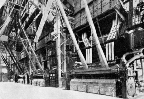
THE FIRING AISLE in the boiler house of Dunston-on-Tyne Power Station. The installation contains twelve boilers, which normally evaporate 1,350,000 lb. of water an hour. The final steam temperature is 840 degrees Fahrenheit, and the safety valve load is 710 lb. per sq. in.