One of the most famous thoroughfares in the world is built on land reclaimed from the River Thames. Known to Londoners as the Embankment, this thoroughfare includes the Victoria Embankment on the north, and the shorter Albert Embankment on the south bank of the Thames
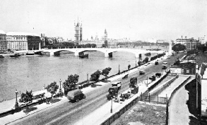
LOOKING EAST along the Victoria Embankment, with St. Paul’s Cathedral in the background. At this part of the Embankment the curve is gradual, having a radius of 8,520 feet. A double tramway track occupies the right-hand side of the roadway.
MILLIONS of people pass along the Victoria Embankment, London, on foot, in tramway cars, in motor vehicles and (under it) in electric railway trains during the course of the year. Comparatively few people appreciate the fact that the thoroughfare, which extends from Westminster Bridge to Blackfriars Bridge, is one of the most successful and important engineering works of its kind in the world.
Two generations have passed since the Victoria Embankment was opened officially in July 1870. At the time it was acclaimed as a triumph of engineering, and such it remains. It swiftly became one of the most famous thoroughfares in the world. Most people refer to it as the Embankment, or the Thames Embankment, although it was not the first to be built nor is it the only Thames embankment.
About the time of its building, engineers were carrying out great changes in central London. They were building railways, creating a proper drainage system, making a new thoroughfare from the Houses of Parliament to the Mansion House, improving old bridges and building new ones. Each of these considerations affected the building of the Embankment.
The Embankment is one of the achievements of Sir Joseph William Bazalgette (1819-91), who was Chief Engineer of the Metro-politan Board of Works. The Board, which preceded the London County Council, was set up in 1855 to supervise drainage, buildings and other matters. Bazalgette was appointed Chief Engineer in that year and remained with the Board until its abolition in 1888. He gave London a main drainage system (see page 519), designed the Victoria Embankment and other embankments and improved the bridges.
Before work began on the Victoria Embankment there were years of suggestions, schemes and commissions of inquiry. It was left to Bazalgette to draw up an original plan, to make the Embankment and to fit it into the wider plans which have given us modern central London. Previously the Strand was the only direct thoroughfare linking the City with Westminster, although the Thames was an important artery of passenger traffic. But the river was important only because traffic conditions in the Strand were bad. There was no thoroughfare between the Strand and the river to give a parallel route to the City.
Steamboats had accelerated the river service. At Charing Cross people walked through the New Hungerford Market, erected in 1833, to Hungerford Stairs. Here, before the building of the Embankment, one million passengers embarked in or landed from river steamers in a year. The New Hungerford Market was pulled down in 1862 to make room for Charing Cross Railway Station. In the following year the Hungerford Suspension Bridge was taken down to make way for the railway bridge, and in the next year work on the Embankment was in progress.
Preliminary work began late in 1863 and the first stone was laid on July 20, 1864, but it was not until July 13, 1870, that the Embankment was opened by the Prince of Wales (afterwards King Edward VII), accompanied by Princess Louise.
The engineers had many difficult problems to solve in making the Embankment. These problems concerned the bed of the river, the height and effects of the tides, the material used in construction, the methods of working, and, particularly, the cofferdams. At this period timber was being replaced by iron. The era of steel and reinforced concrete was yet to come, and electrical machinery, the handy internal combustion engine and the battery of appliances ready-made for the modern engineer were not invented. Men used steam when they could and their hands and their wits when they could not.
Despite these handicaps the Embankment is a wonderful piece of work. A total area of thirty-seven and a quarter acres, previously covered with mud-banks, was reclaimed from the Thames. Nineteen acres were occupied by the road and footway. About ten acres were made into gardens and ornamental grounds for the public, and the remainder became the property of the Crown, of the Societies of the Inner and Middle Temple and other landowners. The net cost was £1,156,981.
Effect on Tides
THE low parapet over which the pedestrian looks at the ever fascinating traffic of the river is the top of an impressive wall nearly 7,000 feet long, averaging over 40 feet high, and having foundations from 16 feet to 30 feet below the bed of the Thames. The curvature of the Embankment is as follows: between Westminster Bridge and Charing Cross Bridge the curve is compound, being set out to radii of 8,800 feet and 1,850 feet; from Charing Cross Bridge to Waterloo Bridge the curve is of a 1,655-feet radius; below Waterloo Bridge and extending to 100 feet beyond the Temple Pier the radius is 8,520 feet. The abutments and piers of the bridges which meet the curved line of wall are tangential to the curve. Except towards Westminster and Blackfriars Bridges, where the road rises, the level of the road was fixed at about 4 feet above high-water mark. The parapet, which has a moulded cap and base, is 3 ft 6 in above the footpath. The height of the roadway was arrived at because of reports made by an expert about 1840 to the effect that no tide, up to that date, had ever risen as high as this point, which was 16 ft 6 in above Ordnance datum line (the line from which all heights are reckoned for surveys). Little more than five years, after the completion of the Embankment a tide was recorded 7 in above the expert’s limit, and other tides nearly equalled the height of the exceptional one. This occasioned great controversy and some alarm. Some Londoners blamed the Embankment for causing high tides.
SUPPORTING THE COFFERDAM used in the building of the Victoria Embankment. When the iron caissons were in position, timbers were fixed against the inner sides of the dam to brace the caissons against the pressure of the water as the tide rose. On the right are the piles which were driven into the clay; their tops were timbered and rails were bolted to the timbers to allow the dredger to be moved along as work progressed.
It was considered, however, that the high tides were due to the dredging of the river bed and to the improvements to the bridges which, by widening the spans and reducing the obstruction to the ebb and flow gave the water more scope. At one period Old London Bridge acted as a weir and the current above it was so slack that in exceptionally cold winters the Thames sometimes froze from shore to shore.
In January 1928 a remarkable spring tide, due to abnormal causes, flooded the roadway of the embankments. At places above the Victoria Embank-ment, this tide drowned a number of persons and did much damage. At high water during extraordinary spring tides the vessels in the river appear to be above the level of the road.
The Embankment was built by three separate contractors. The first sector was from Westminster Bridge to Waterloo Bridge, the second from Waterloo Bridge to the east end of the Temple, and the third thence to Blackfriars Bridge. It was decided to build whole-tide cofferdams, but there was much discussion as to the most suitable type. The greater part of the dam was formed of two rows of timber piles with puddle filling between them, and the remainder consisted of iron caissons which were sunk into the bed of the river.
The first step was to determine the nature of the substrata. Fourteen boreholes were sunk along the intended line of the Embankment wall, seven between Westminster and Waterloo Bridges and seven between Waterloo and Blackfriars Bridges. These disclosed considerable irregularity in the depth of the surface of the clay, the difference in the levels between the third and fourth boreholes (between York Gate and Charing Cross Bridge) being about 16 feet. The borings from Waterloo Bridge to Blackfriars Bridge showed a more uniform level.
Sixty-one cross-sections were taken at intervals along the old shore walls, extending from these towards the river to a little beyond the line of the Embankment wall. The mud in this area was removed in barges, and then the whole space was filled with ballast and built up about 15 feet above datum line for a width of 120 feet at the back of the new wall, and from 15 feet to 13½ feet above this datum for the remaining width, to the original walls or banks.
In the neighbourhood of Waterloo Bridge the difficulties of building an effective dam were acute. Many attempts were made to devise a dam of iron, or of iron and wood. The plan adopted was devised by Joseph Phillips, of the Charing Cross Railway Works, who had had experience of building foundations under water in iron for railway bridges. His plan was to build a dam of iron caissons, a proportion of the caissons to remain as part of the permanent work, after they had been filled in with concrete to form an apron to protect the foundations of the embankment.
The caissons were sunk by excavating the ground within them. They were well weighted with 9-cwt iron blocks cast to the shape of rings and piled upon timbers which formed the strengthening struts. The great problem was to excavate the material. Three different methods were tried. In one method men worked inside the caisson and the water was kept down by means of a chain-and-bucket pump. In the second method men worked inside the caisson and the water was kept out by pumping air into the caisson. In the third method the material was excavated by a dredger which worked an endless chain of buckets.
Pneumatic Caisson
AT this period little was known of caisson work, and the three methods were in the nature of an experiment. In the first method men dug the soil, put it into skips, which were raised and emptied while the chain-and-bucket pump raised the water from the sump inside the caisson and tipped the water into a wooden chute, which discharged it into the river. By this means six cubic yards were excavated a day.
A pneumatic caisson was used in the second method. A wrought-iron plate with a manhole cut into it was bolted to the upper end of a caisson ring which formed the cover of the caisson. Under the manhole was placed an iron chamber large enough to contain a man. The chamber had flaps, or doors, worked by equalizing the air pressure in the interior of the caisson with that in the chamber. The chamber had two pipes, one leading into the caisson and the other to the exterior. To gain access to the caisson a man entered the chamber through the manhole in the cover. When the air pressure in the chamber had been raised to that in the caisson he opened the lower door in the chamber and descended a ladder leading into the lower part of the caisson.
He put the soil he dug into a bucket which was attached to a wire cable which passed through a stuffing box in the cover of the caisson. The filled bucket was pulled up to the level of the lower door of the chamber inside which a man was stationed. This man opened the lower door so that the bucket could be drawn into the chamber. Then the lower door was closed and the upper door in the chamber was opened and the bucket was passed out. The pneumatic caisson enabled 5·31 cubic yards a day to be excavated.
A SECTION OF THE VICTORIA EMBANKMENT, showing the position of the tunnel for the Metropolitan District Railway, now part of the London Passenger Transport Board’s Underground railway system. The subway on the left carries gas and water pipes and, with the sewer, forms a buttress to the wall. Subway, sewer, and river wall are tied into one another by cross-walls.
The third method, enabling about 10 cubic yards a day to be excavated, used a telescopic dredger. Because of the narrowness of the opening in the caisson the ladder carrying the buckets had to operate in a vertical position. It was fixed in the centre of the caisson and its weight helped to force more material into the hole scooped out by the buckets. The buckets were hinged and when they had been raised, filled with material, they were tipped by arms on to the camshaft so that the contents fell into a chute which carried the earth into a barge. When the buckets scooped material out of the depths, the ladder lowered deeper so that the buckets could bite into new material. When the iron caissons for the cofferdam were in position timbers were fixed against the inner sides of the dam to brace the caissons against the pressure of the water as the tide rose in the river outside the dam. In every cofferdam one or more of the caissons were fitted with rings provided with sluices. These were fixed a little above low-water level and were opened or closed by rods worked by a lever from the top of the dam. Tidal water could be let into the caisson in an emergency or, at low water, water inside the caisson could be discharged into the river. Water which was inside the cofferdam could be discharged by passing it through the caissons fitted with sluices. If necessary the tide could be allowed to flow and to ebb within the cofferdam by means of the sluices in the caissons.
Land water gave a great deal of trouble. A sump was sunk into the clay within the cofferdam to drain it, and chain-and-bucket pumps were rigged to raise the water and discharge it into the river through wooden chutes. In some places the pumping arrangements failed to cope with the inflow of water. The trench which was dug to enable the foundations of the Embankment wall to be built was flooded by several feet of water. No matter what they did the men could not get rid of the water. But the concrete for the foundations was put in. Boxes of wood and iron were made and provided with arms that opened them. The concrete was put into the boxes, which were closed and lowered into the water. When the boxes were in position they were opened and the concrete was deposited.
Foundation Trenches
AS THE trench for the foundations was below low water the sluices in the caissons could not operate. When the work progressed and the wall was built up a few feet above low water the sluices were generally able to discharge the water which had accumulated in the workings during the rise and fall of the tide, and the pumps were not needed.
One method of excavating the trench for the foundations was by steam dredgers. Piles were driven into the clay along the length of the trench and timbers were placed on the tops of the piles. Rails were bolted to the timbers. The rails enabled the dredger to be shifted to a new position when a site had been excavated.
The greater part of the work was protected by a wooden cofferdam. When the time came to demolish this, a problem arose because the piles were not permitted to be withdrawn from the clay and it was decided to cut them off several feet below low-water mark. To do the cutting a special machine was devised. This pile-cutter comprised a steam engine and machinery which was mounted on a frame with wheels. Rails were bolted to beams which rested on the heads of the piles to be cut, and the pile-cutter was shifted along the rails. The steam engine turned a spindle which rotated a circular saw. The spindle worked in a guide at the end of a movable arm by means of which the saw could be pressed against a pile. The machine cut from thirty to forty piles a day.
SEEN FROM WATERLOO BRIDGE - the Victoria Embankment soon after its completion. On the left is Somerset House, the east wing of which is occupied by King’s College. Beyond it, to the right, is the site on which Temple Underground Station now stands. The gasholders and factories in front of St. Paul’s Cathedral have long since been demolished.
The trenches for the foundation of the wall were dug 20 feet below datum line. Layers of concrete were placed in position and brought up to a level of 12½ feet below datum. Then a bed was formed to receive the footings of the brick wall. The Portland cement was tested by subjecting it to a tensile strain of 250 lb per square inch after seven days’ immersion in water. The concrete made from the cement was mixed in the proportion of one part cement to six of ballast for the wall up to a level of 8 feet below datum. Above this height of wall the proportion of cement to ballast was 1 to 8. The sewer and the subway for gas and water pipes were built to form part of the structure. They were placed under the footway next to the river and formed a buttress to the wall. The sewer varied in diameter from 7 ft 9 in to 8 ft 3 in, and the subway was 7 ft 3 in high and 9 feet wide.
The brickwork was laid in courses at right angles to the face of the brick and was bonded with stone facing. The sewer, supported on concrete foundations and built of brickwork 13½ in thick, was incorporated with the concrete and the wall. When the wall and the concrete covering the sewer were raised to a level of nearly 7 feet above datum the brick subway was built over the sewer. The side walls of the subway were 18 in thick, and the brick arch was 13½ in thick. The subway was built on a level for most of its length, exceptions being where it crossed the sewer storm overflow chambers and near Waterloo and Westminster Bridges. In some places the floor was built with a brick invert instead of concrete.
Subway, sewer and river wall were tied into one another at 6 feet intervals by cross walls. The space between the subway and the wall was filled with brickwork. A counterfort (strengthening structure) of brickwork was built over and round the arch of the subway to a level of 16 feet above datum line at the back of the Embankment lamp pedestals, to receive a washer plate for attaching mooring rings.
The stones facing the granite wall were fine axed on the river front to a curved batter, and the backs of them were scabbled (levelled without a smooth surface) to a fair surface to join the brick backing. From five feet below the roadway all exposed surfaces were chiselled, and no joint over an eighth of an inch thick was allowed. The granite was from the Duke of Argyll’s quarries, which supplied the stone for Waterloo Bridge.
Subway to Houses of Parliament
On the river face were fixed lions’ heads carrying mooring rings. Granite piers with recesses for pontoon landing stages and, at other places, stairs for landing passengers from small boats, break the uniform line of the Embankment. When the work was completed some people criticized the lack of statuary. Cleopatra’s Needle, which was brought from Egypt, was not erected until 1878, and the memorials to the Submarine Service and to the Royal Air Force are recent.
Considerable effort was expended on the piers and the boat stairs. The piers were built at Westminster, Charing Cross and Waterloo Bridges. Those for small craft were placed between Westminster and Charing Cross, and between Charing Cross and Waterloo Bridges, and landing places for large and small craft were combined at the Temple Pier.
The landing stages consisted of timber platforms carried upon iron pontoons. Waiting rooms were built on the platforms. Wrought iron from the cofferdam caissons was made into the plates for the pontoons. Bridges of iron girders with timber flooring linked the piers with the floating stages. Nowadays Westminster Pier is the only one which has any considerable passenger traffic.
When Westminster Pier was built a subway was driven under the Embankment to link up with Westminster Station and the subway that leads to the Houses of Parliament. The building of the pier was a formidable work. The foundations of the pier and of the wall were carried down in brickwork and masonry to a bed of concrete. Three flights of stone steps descending from Westminster Bridge were built. In the space under them a reservoir was built to flush away mud which would otherwise have accumulated in the recess formed by the pier. A culvert was built to flush the floor of the recess. Elaborate, but different, flushing arrangements were built at the pier adjacent to Waterloo Bridge.
BUILDING THE ALBERT EMBANKMENT, on the south side of the Thames, above Westminster Bridge. This old woodcut shows the scene from the present site of Lambeth Bridge. St. Thomas’s Hospital now stands between Lambeth Bridge and Westminster Bridge.
Had the constructors imagined that in future years the Thames would cease to be an artery of passenger traffic for Londoners, they would probably not have gone to the trouble of building such elaborate piers. At the time of the completion of the work the excellence of the piers was acclaimed as one of the outstanding features of the whole construction. The iron caissons appealed to the imagination of the public, and they were described as an indication of a new era where iron was displacing wood for ship-building and stone for bridge building.
The footway of the Embankment was opened for public use from Westminster Bridge to the Temple on July 30, 1868, but the road could not be used because of the work on the Metropolitan District Railway. The railway work did not begin at the Whitehall end until 1869, and the railway was not completed until May 30, 1870. The rails were laid about 17½ feet below the surface of the roadway. The roadway was supported by cast-iron girders and brick arches. The trains were then pulled by steam loco-motives, and east of Charing Cross (District) Station there were three necessary openings for ventilation. Within about six weeks of the completion of the railway the road was finished.
At first the opening day was arranged for July 25, 1870, but on July 8 word was received that Queen Victoria desired to open the Embankment on July 13. This was a surprise, but those concerned determined to make a great effort to accelerate and get the work completed in time.
Last-Minute Disappointment
About 2,000 men toiled at their utmost speed day and night. They won the race against time, although there came a last-minute disappointment. Queen Victoria was indisposed. The Prince of Wales (King Edward VII), however, deputized for her, and the Victoria Embankment was opened on the appointed date.
After this, the railway was continued eastward. When the railway workers were out of the way it was possible to open Queen Victoria Street, and London had a magnificent new thoroughfare from the Houses of Parliament to the Mansion House. The name of Queen Victoria is preserved along the route from Victoria Station by way of Victoria Street, the Victoria Embankment and Queen Victoria Street. For some years there was no adequate access to the Embankment from Charing Cross for vehicles coming from the west and north-west. To remedy this defect, land was bought from the Duke of Northumberland. Northumber-land Avenue was built and was opened in March 1877. This enabled traffic to cut through from Trafalgar Square and Charing Cross to the Embankment.
On the south side of the Thames from Westminster Bridge to Vauxhall Bridge is the Albert Embankment. This is 5,200 feet long and was begun and completed while the Victoria Embankment was under construction. The cost was £1,014,525. On ground made available for building, St. Thomas’s Hospital was built. The hospital was previously in Southwark, but had to be demolished to make way for railway works. The Albert Embankment was opened in 1869.
On the northern bank of the Thames the river was embanked from Millbank to Chelsea Hospital about 1854. This embankment was extended to Battersea Bridge between 1871 and 1874 at a net cost of £269,591, and this marked the fulfilment of the plans undertaken by the Metropolitan Board of Works for embanking the river. There have been improvements and alterations in recent years, particularly near Lambeth Bridge.
ON THE SOUTH SIDE OF THE THAMES, the Albert Embankment extends from Vauxhall Bridge to Westminster Bridge. The illustration shows Lambeth Bridge, which was opened by HM King George V in 1932, with Thames House and Imperial Chemical House on the left and St. Thomas’s Hospital on the right. The Albert Embankment is 5,200 feet long and cost £1,014,525 to build. It was opened in 1869.