A network of complicated electrical apparatus, entirely automatic in its action, now controls the traffic flow at nearly every important road intersection in the large towns and cities of Great Britain
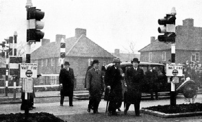
TRAFFIC SIGNALS OF SEVERAL TYPES are visible in this illustration, which shows Mr Hore-Belisha (right) inaugurating the installation at St Helier Avenue, near Morden, Surrey. Mr Hore-Belisha is operating the pedestrian signals by crossing the path of a light beam projected from the standard on the right to the photo-cells mounted in cases on the standard on the left. In the background are special signals for the cycle track at the side of the road.
AUTOMATIC traffic signals are almost as much of a commonplace in our daily life as are telephones, radio and other comparatively modern inventions. So familiar are they to everyone who uses the roads that it seems almost impossible to believe that the first British installations were put into action as recently as 1928.
The enormous increase in the volume of traffic, particularly in the congested areas surrounding large towns and cities, has made automatic control of traffic flow an absolute necessity, and the familiar red, amber and green lights are the outward and visible sign of this control. The control box standing near the signals, however, contains the “brains” of the system, and of these the average road user knows little or nothing. Traffic control methods develop from year to year, although the appearance of the signals may not change.
The first automatic signals installed on the roads of Great Britain were of the fixed time-cycle variety. They were entirely automatic in action, but the vehicles played no part in the operation. Signals were installed at a road junction, and mechanism operated those signals in such a way that east-west traffic had the right of way for a fixed period, after which it was given the “caution” and “stop” signals so that north-south traffic could have the right of way for a fixed period.
This system may possibly be ideal for a simple road intersection at which the north-south and east-west traffic flow with equal density. Even then, however, the length of the time-cycle should be variable, or there will inevitably be unnecessary delays when little traffic is about.
The inability of the fixed-time system to adapt itself to irregularities in traffic flow led to the development of signals actuated by vehicles on the road.
Traffic signals of the type known as “Electro-matic Vehicle-Actuated Signals” were first installed in Europe at the junction of Cornhill and Gracechurch Street, in the City of London, in 1932. They have rapidly come into their own, and few fixed-time signals are now in action in Great Britain. Many of the fixed-time signals that were installed in London have since been converted to the new system, and more are due for conversion.
CROSSING THE DETECTOR STRIP, which signals the approach of a vehicle by transmitting an impulse to the control box. Detector strips are mounted flush with the road surface and the mechanism is hermetically sealed to make it immune from the action of rain or snow.
The ideal system of street traffic control at an intersection or a junction is one in which every vehicle approaching, from either direction, automatically secures the right of way at the earliest possible moment, with due regard to the claims of other vehicles. Such an ideal may appear to be impossible of attainment when the complexity and volume of modern traffic is borne in mind; but the seemingly impossible has been achieved, and there is in everyday operation a system of traffic control that seems almost capable of thinking for itself.
The “Electro-matic” apparatus consists of three main parts electrically linked together. The first is the detector strip, let into the road surface, by means of which vehicles indicate their presence to the -second part, the control box. This box houses the mechanism which “receives the instructions” from the detector strips and operates the third part, which is any standard type of traffic signal.
The detector unit, below the road level, is hermetically sealed in position, and its operation therefore cannot be affected by snow, rain, ice or hail. The working parts are surmounted by a rubber composition tread which is depressed by the weight of a vehicle passing over it. The detector is set at a distance from the intersection dependent upon the nature of the road and upon the speed and volume of traffic using it. Basically, it is merely a simple switch which closes a circuit whenever a vehicle passes over the strip.
The controller is a robust piece of mechanism which transfers the switching operations to the signals in a regular cycle: red (stop), red and amber (caution), green (go), amber (caution), red (stop). Since it is often impracticable for the impulses received by the detector strips to be passed on instantaneously to the signals, the control mechanism uses several timing devices, so arranged that every vehicle is given a through passage as soon as a safe opportunity occurs.
The signal lanterns are of the conventional colour-light pattern, and are so arranged at a road intersection that one of them, at least, is clearly visible to traffic at any point on or near that intersection. The most convenient manner of placing the signals is decided upon by the local traffic authority.
THE CONTROL BOX - the nerve-centre of automatic traffic signal mechanism. Its function is to translate the impulses received from the vehicle detector strips into the appropriate changes of signal lights.
A clear understanding of the principles of operation is most readily gained by considering a simple right-angled intersection of two roads. There are four detectors - one in each approach road - and probably four sets of signals, some of which, however, may be duplicated to give better visibility. In nearly all instances duplicate lights are placed at the farther side of the road junction, for the convenience of drivers of saloon cars, who cannot easily see the lights immediately adjacent to them when they have stopped.
Suppose a vehicle travelling from north to south arrives at the intersection and finds the green light showing, giving the driver the right of way. The vehicle proceeds across the detector strip and, although no visible change occurs, the impulse which it transmits to the controller ensures safe passage; that is, it makes it impossible for the lights to change until that vehicle has had sufficient time to get clear of the intersection. The time interval secured is proportionate to the speed of the vehicle; a horse-drawn lorry would press the switch contacts into the “closed” position for a greater period of time than would a fast-moving car, and would receive a longer period of green.
Consider next a car approaching from the east. It finds the signals against it, but immediately it passes over the detector strip - if the north-south travelling vehicle has cleared the cross road - the lights change in its favour and remain at green for east-west and west-east traffic.
AUTOMATIC SIGNALS FOR PEDESTRIANS are among the more recent developments in traffic control. A light-beam projector (far left) shines on a photo-electric cell mounted in a receiver unit (left), the two components being separated by a gangway through which pedestrians are “shepherded” by guard rails. Each interruption of the beam transmits an impulse to the control box and ensures that the signals will change at the first safe moment.
Suppose two cars approach the intersection simultaneously. If one crosses its detector strip the merest fraction of a second before the other, it is given the right of way and the second car is held up until a sufficient interval of time has elapsed for the first to get clear. If the two operate the detectors at the same instant, a special device automatically gives preference to one. Finally consider continuous streams of traffic on either highway. If the lights are showing green to north-south and south-north traffic, each successive vehicle to cross the detector strip will extend the right of way to ensure its crossing in safety. Meanwhile, however, vehicles on the other road will be waiting, and one or two of them will have crossed their detector strips, thereby informing the control box that they are there. As soon as a gap occurs in the other traffic stream, the lights will change and give the right of way to the, cross traffic, which, as soon as it begins to move, will pass on a long succession of impulses to its detector strips.
This procedure, it might be imagined, would cause a kind of constant fight between east-west and north-south to secure a right of way. A special control, however, prevents such an occurrence. It initiates a second timing interval which determines the maximum period for which continuous traffic in one direction can keep traffic - even a single vehicle - waiting for its right of way in the other direction. In other words, vehicles proceeding in one direction may extend their right of way indefinitely with one proviso - that they must sacrifice the right of way at the end of a predetermined interval if cross traffic requires it. Thus one stream of traffic cannot secure permanent precedence over another; waiting traffic is always passed through the first available gap and each road secures the right of way in a varying ratio, corresponding to the ever-changing density of traffic.
Should the traffic distribution on the two roads be equal, the signals will thus change at a fixed time interval, determined by the settings of the various controls in the box.
So flexible is the system that it can be extended to meet any circumstances that are found on modern roads. T-shaped junctions, offset intersections, multiway intersections, circuses, minor roads intersecting arterial highways - all can be dealt with in such a way that the traffic is handled in the most expeditious manner possible.
A SIMPLIFIED CIRCUIT DIAGRAM showing the electrical principles used for one type of traffic signal. The important components are the variable resistance R, the condenser C, the neon discharge tube NL, the relay which operates the signals and the detector strip D1. The way in which the circuit operates is fully explained below.
The diagram above shows the basic arrangement of the control mechanism used in the “Electro-matic” system. Other systems are controlled in different ways, but this particular method may be regarded as a typical instance of the utilization of certain electrical properties and their conversion to the operation of a purely mechanical sequence of events.
A 412-volts source is applied across the points “+” and “—”. The condenser (C) becomes charged, the time it takes in doing so being dependent upon the setting of the variable resistance (R). This resistance is one of the variable factors in the control box. Across the condenser (C) are wired three units - a neon discharge tube (NL), a relay actuating the lamp signals, and a detector strip (D1) in the road.
The neon tube has the peculiar property that it will pass no current until the voltage across it has reached a certain figure. When the condenser has become charged to this particular voltage (or any higher voltage), a vehicle passing over the detector strip (D1) will complete the circuit. Current will pass through the neon tube and through the relay, which will change the signals - in this instance from red, through red and amber, to green.
Amber Timing Switches
There is, however, another circuit connected across the condenser. This secondary circuit comprises a discharge resistance (DR) and the other detector strip (D2). Its operation is most simply explained by imagining that a vehicle is just about to start the sequence described in the previous paragraph. The lights are showing red, but the vehicle is approaching the detector strip and the driver, knowing something about the operation of vehicle-actuated signals, hopes to see them change as he runs over the strip.
A fraction of a second before he reaches it, however, another vehicle passes over the detector strip (D2) in the intersecting road. This completes the secondary circuit and discharges the condenser. Thus the first driver, although he duly completes the circuit by running over the strip D1, does not change the lights, as there is not sufficient voltage to cause the neon tube to flash over.
He will have to wait until the condenser has charged up to a sufficiently high voltage to do this - and that operation will occupy an interval of time that is adjusted by the various controls in the box, to meet the particular requirements of the road intersection under consideration.
This represents only the bare essentials of the circuit arrangement, which becomes highly complicated as various supplementary units are added. There is, for example, a subsidiary circuit whose function is to limit the time for which operation of the detector contacts D2 may prevent the neon tube NL from flashing. The relay operates a solenoid which takes charge of the complete cycle of warning signals. Each impulse handed on by the relay takes the signals through the next phase of the sequence.
At some intersections road conditions may be such that a vehicle leaving a junction may cross the detector strip which is intended for operation only by traffic proceeding towards the junction in the opposite direction. Narrow roads and stationary vehicles often give rise to such a situation. In these instances a unidirectional detector strip may be provided - that is, one which will operate only when a vehicle crosses it in the desired direction. The upper detector strip is divided into two sections, and only if these are depressed in the correct order will an impulse be handed on to the traffic signals. Drivers who reverse over a traffic strip and fail to operate the signals are often puzzled, but this explains the reason for their failure.
The adjustments provided in the control box for a simple road intersection have several functions to perform. There are two “maximum timing switches” for adjusting the maximum period during which continuous traffic on one road can detain a vehicle on the other.
There are two “amber timing switches”, for adjusting the period for which the amber light shows, in accordance with the requirements of traffic. If a road loses its right of way because of a gap in the traffic on the other road, only a short amber period is necessary; on the other hand, if a continuous flow of traffic has to be interrupted, a longer amber period is desirable. Certain signals of the “Electro-matic” type therefore incorporate a feature known as “amber extension”, which automatically adjusts the length of the amber period, according to the flow of traffic at the particular instant when the signals are changed.
THE CONTROLLER comprises a solenoid-operated camshaft which changes the lights in six steps; four relays; two gas discharge tubes; two condensers; and a group of variable resistances which can be set to give any desired time intervals between the various operations of the traffic signals. Two groups of switches are used also for controlling the timing in certain circumstances.
The “vehicle interval timing switches” determine the period which a vehicle is allowed for moving from the detector strip to the far side of the intersection. Each vehicle, as it crosses its detector, secures its own safety interval in accordance with its speed.
The “ initial interval timing switches ” are provided to insert a further fixed period for the passage of a vehicle which has been held up at the crossroads, as it will require more time to cross than would a vehicle which has crossed the detector with a “flying start”.
All the foregoing facts have been concerned solely with the simplest type of road intersection. The extreme flexibility of the electrical principles used, however, makes it possible to design a system of automatic signalling which will cope with the requirements of the most complicated type of junction.
In addition, pedestrians often have to be protected against traffic and against themselves, and many really complex road junctions are fitted with a system of signalling that provides safe periods during which pedestrians may cross the roads.
In some instances the system is incorporated automatically. In others it is necessary for pedestrians to push a button, which will secure right of way for them at the first safe moment. A newer technique which is being developed, however, makes use of light rays and photoelectric cells.
Thus shoppers with their arms full of parcels, business men with cases and umbrellas, and children with no responsibilities at all are relieved even of the necessity of pressing a button. They are guided, by the use of barriers or chains, through an aperture across which a beam of light is shining on a photoelectric cell.
The passage of a pedestrian momentarily breaks this beam and passes on an impulse to the control box. If traffic conditions are suitable, the pedestrians will be given passage at once. If, however, it is necessary to interrupt a stream of traffic, the impulse will be stored in the capacious “brain” of the control box, which will “remember” it and put it into action at the first suitable opportunity.
“Repeat Pulsing”
The photoelectric cells for this work are mounted in specially screened boxes in such a way that they are sensitive only to the light from the special projector on the opposite side of the gangway through which the pedestrians pass. So long as the light beam from this projector is falling on the cell, the equipment remains quiescent. As soon as it is interrupted, a relay comes into operation.
A recent development in traffic control is known as “Electro-matic Repeat Pulsing” equipment. This represents a real step forward in the co-ordinated control of more than one road junction. Under the system at present in general use, traffic passed through one intersection may be held up at the next. “Repeat Pulsing” provides to a distant set of signals the foreknowledge that traffic is approaching, and advises them to have the right of way ready when this traffic arrives.
When the traffic crosses one intersection, therefore, during a green “Go” period, the impulses are repeated to the next control box along the road. Should they arrive during a “Stop” period, they are stored up until cross-traffic ceases, and then come into operation. In addition, they are passed on yet again to the next set of signals.
This system has been adopted for Regent Street and Piccadilly in London, and for Hope Street and Renfield Street in Glasgow. It was in Glasgow that “Repeat Pulsing” was first put into practical use.
Intensive research is being carried out with even more complex schemes, and it seems probable that in the future we shall have a complete system of control of road traffic of all kinds which will be more reliable than any form of manual control could possibly be.
The success of the earlier work of the engineers may be judged by the fact that it is already realized that vehicle-actuated traffic control minimizes loss of time and congestion, and is more readily obeyed than any other because it never stops traffic without a reason.
Thousands of pounds are spent on every mile of a modern road, and the maximum return can be secured only by ensuring that the greatest possible volume of traffic can use that road in safety, without congestion or delay.
It is seldom appreciated that average speeds in cities are often as low as five miles an hour. Every mile an hour by which they can be raised represents a high percentage of the existing speed, and it has been stated that an increase of a quarter of a mile an hour will increase the traffic flow by five per cent.
Excellent roads through the open country have made possible such high average speeds between cities and towns that public safety demands control at many places where, only a few years ago, nobody but a foolish road-user would have found danger. Automatic traffic signals are an important part of this control, and their usefulness increases every day, as the density of road traffic becomes greater.
SECTIONAL VIEW of a detector strip. The contacts, mounted in a recess in the road surface, are operated by a stout rubber tread over which vehicles pass. The strip shown is of the simple type. Certain detectors are so arranged that they respond to the movement of traffic in only one direction.


 TRAFFIC SIGNALS OF SEVERAL TYPES are visible in this illustration, which shows Mr Hore-
 CROSSING THE DETECTOR STRIP, which signals the approach of a vehicle by transmitting an impulse to the control box. Detector strips are mounted flush with the road surface and the mechanism is hermetically sealed to make it immune from the action of rain or snow.
 THE CONTROL BOX -
 AUTOMATIC SIGNALS FOR PEDESTRIANS are among the more recent developments in traffic control. A light-
 THE CONTROLLER comprises a solenoid-
 SECTIONAL VIEW of a detector strip. The contacts, mounted in a recess in the road surface, are operated by a stout rubber tread over which vehicles pass. The strip shown is of the simple type. Certain detectors are so arranged that they respond to the movement of traffic in only one direction.