The most practicable and economical way to carry road traffic across a waterway is often by a transporter bridge. No approach viaducts are necessary, although the permanent span is at such a height as to give plenty of headway for shipping. River traffic is interrupted only by the crossing of the suspended transporter car
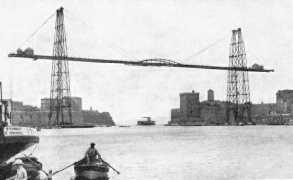
THE ENTRANCE TO THE OLD HARBOUR of Marseilles, France, is spanned by a transporter bridge designed by Arnodin, the man who was responsible for building many such bridges. The bridge at Marseilles has a span of 540 feet, and was built in 1905. The towers reach to a height of 282 feet and the girders carrying the traverser are 164 feet above the water.
ALTHOUGH the principle of the transporter bridge is not new, its application in its modern form is comparatively recent. Transporter bridges are the logical development of the ropeway. The first important applications of the principle were made in France.
Years ago, a crofter in the Scottish Highlands wished to make a short cut from his cottage across a turbulent mountain stream, which separated it from the main road. So he stretched two stout cables between two trees which grew on either side of the stream. The stream was too wide for an ordinary plank bridge, and he, being a poor man, could not afford to build a better structure solely for his own and his family’s convenience. He compromised with these two ropes. He and his wife could cross the stream by walking on one rope and holding on to the other, which was several feet above it. This was too perilous a performance for his young children, and their careful father rigged up a pulley arrangement whereby he could haul them across, one at a time, in a suspended game-bag. He had not produced a transporter bridge in the modern sense of the term, but at least he had applied the idea of the transporter.
It was a French engineer, M. Arnodin, who first applied the principle of the transporter, or travelling platform, to large-scale bridges. Arnodin was faced with the problem of bridging navigable rivers lying between flat shores, and at the same time avoiding the trouble and expense of providing long approach viaducts at either end to bring traffic to a height sufficient to clear the masts of passing ships.
There were various possibilities. The drawbridge dates far back to the middle ages. The balanced drawbridge dates from the time when the weight of a portcullis coming down compensated for the weight of the bascule going up. From this there developed the idea of the modern rolling bascule bridge. Then the swing bridge offered another solution. It had the disadvantage of placing an obstruction in the middle of the fairway. The rolling bascule bridge had its advantages, but even a bridge with two bascules, such as the Tower Bridge in London, was subject to limitations of length. It is not practically possible to build even a double bascule bridge across a gap of, say, 1,000 feet.
Arnodin aimed at producing a bridge which should be able to cross the widest gaps without elevated approaches and without interfering with the fairway, whether above or on either side. To do this, he devised a clear span, supported on either cantilever or suspension principles, at a great height above the water, and supported at either end by a tower or by a pair of towers. On the underside of the span he mounted rails, and on these he set a traverser or trolley, mounted on flanged wheels and proof against derailment. The traverser was to be self-propelling, or it could, if necessary, be towed backwards and forwards by cables operated by a winding engine at either end of the structure. So far, the invention resembled a huge gantry crane without the usual hoisting tackle.
From the overhead trolley Arnodin supported, by girders or stout cables, a large platform capable of carrying foot passengers and road vehicles. This was at ground level, thus eliminating the bugbear of the approach viaduct. The vehicles wore driven on to this platform or transporter at one end of the bridge. The gates of the transporter, and those leading to it, were then locked, the motorman applied his power and the trolley overhead moved across the bridge, carrying the transporter with it. On the other side the incoming traffic was released, and then the performance was repeated. Thus the waterway under the bridge was interrupted only during the passage of the transporter, which took at the most two or three minutes, and generally less.
The transporter bridge thus serves the purpose of a ferry, without the ordinary ferry’s disadvantages. It is expeditious, with no delays for berthing and no difficulties attending the embarkation or disembarkation of vehicles. It is independent of wind and weather. It is much cheaper to build than an ordinary high-level bridge, but it has its limitations. For a continuous stream of heavy traffic it is unsuitable, as constant movement across the bridge is not possible. A giant transporter bridge across the River Tyne at Newcastle, or across the Hudson River on the site of the Washington Memorial Bridge in New York, would cause continuous congestion and reduce traffic on the surrounding roads to chaos.
But where traffic is so heavy, the great expenditure involved by a high-level bridge allowing for a continuous flow of traffic is fully justified, and the transporter bridge does not need consideration. The transporter bridge is designed for a stated purpose, namely for carrying on communication between two important, but not congested roads on either side of a river.
One of the best examples of a transporter bridge is the well-known structure which crosses the River Mersey between Runcorn in Cheshire and Widnes in Lancashire. Throughout the nineteenth century traffic between Lancashire and Cheshire was at a disadvantage. Right down the wider reaches of the Mersey ferries provided the only means of communication between the adjacent counties. Even before railways came there was a need for a bridge of some kind, preferably close to Runcorn, where the river narrows before finally widening out into its estuary between Liverpool and Birkenhead.
Across the Mersey
As long ago as the first two decades of the nineteenth century the possibility of bridging the Mersey between Runcorn and Widnes was being considered by a Select Committee composed of “Liverpool Merchants, Noblemen, and Gentlemen of both Counties, as well as of Staffordshire”. Observe that the “Merchants’’and not the “Noblemen” came first. The industrial revolution was then in course of development. To this Select Committee, in 1817, Thomas Telford submitted plans for a big suspension bridge with a clear span of 1,000 feet, to carry the Runcorn-Widnes traffic. The Select Committee approved of Telford’s plans, but did nothing. The original model, however, shows the design to have been the forerunner of Telford’s masterpieces at Conway and across the Menai Straits.
Years of stagnation followed, in spite of the Select Committee. Several engineers in addition to Telford made proposals, but nothing was done. The coming of railways was a considerable spur to industry in Lancashire and Cheshire, which were among the first counties to enjoy the benefits of the new mode of transport. But the railways had their own means of crossing rivers, which they kept much to themselves. They had enormous reserves of capital behind them. Thus the first span across the Mersey at Runcorn was a high-level girder bridge carrying a double line of rails, to the exclusion of all road vehicles. This structure was completed in 1868.
RUNCORN TRANSPORTER BRIDGE spans the River Mersey and the Manchester Ship Canal between Widnes, Lancs, and Runcorn, Cheshire. The bridge is parallel with the bridge and viaduct that carry the L.M.S. line from Liverpool to Crewe. The span of the transporter bridge is 1,000 feet and the four towers are 190 feet above high water.
With the railway bridge there, it was beyond anyone’s means to risk building a similar structure parallel to it for the sole benefit of road traffic. For road traffic there should be a cheaper form of bridge. The transporter bridge was ideal, but the transporter bridge was then still an unknown factor. It did not remain so for long, however. A few years later, round about the middle ‘seventies, a Hartlepool engineer named Charles Smith designed the forerunner of the modern transporter bridge as a means for crossing the Tees at Middlesbrough, Yorks. The place in question was not unlike the Runcorn-Widnes gap. But people thought purely in terms of railways at that time, and Smith’s proposals were not taken up.
Even the railway monopoly could not break the need for a bridge at Runcorn for road vehicles. Rather, it increased it, because of the great traffic in drays and coal carts which came to feed the big freight centres on the Widnes side. Then came the Manchester Ship Canal, the works of which included extensive docks at Weston Point and Runcorn.
A French Pioneer
A new bridge became more of a necessity than ever. Meanwhile the transporter bridge had not remained a dormant invention since Smith had proposed spanning the Tees with such a structure, for it was during this time that Arnodin took up the idea.
Arnodin built on the Continent a number of suspension bridges in which traffic was maintained by a transporter car supported from a trolley running on overhead rails. He built one across the River Seine at Rouen, and another across the River Charente near Rochefort. In Spain he spanned the River Nervion at Bilbao with a third suspension-transporter bridge. A fourth he erected in Tunisia, across a canal. Turning again to France, he built a cantilever-transporter bridge across the river at Nantes, the shoreward cantilevers being anchored by huge counterweights. All these early transporter bridges were on a rather small scale, but they worked exceedingly well and showed themselves to be ideal for linking up important road systems divided by intervening rivers or harbour mouths, where the density of traffic did not necessitate or justify the cost of a continuous high-level bridge.
One of the best and most notable of Arnodin’s bridges spans the mouth of the Vieux Port or Old Harbour at Marseilles. The bridge is a lofty structure. It can be seen for many miles and is one of the most prominent of the many landmarks of Marseilles.
Thus the transporter bridge had been tried and satisfactorily proved by the end of the nineteenth century. It was the solution for the difficulties which were being experienced to an increasing extent upon the Mersey in England. There were Runcorn and Widnes, each with its boundary formed by a bank of the Mersey. At the narrow neck between the two towns the banks were only 1,300 feet apart as the crow flies. Yet the distance between Runcorn and Widnes by road was no less than 14½ miles by the shortest route.
THE TRANSPORTER CAR of the Pont Transbordeur, which spans the River Seine at Rouen, France. This was one of the first of the transporter bridges built by Arnodin. Traffic is carried in a car which is suspended from a trolley that runs along the girders of the bridge high above the waterway. Wheeled traffic is carried in the middle of the car and foot passengers on either side.
At the end of the last century a company was formed for the purpose of spanning the Mersey at this point with a large transporter bridge which should embody the principles envisaged by Smith on the north-east coast of England and carried out by Arnodin on the Continent. Such a bridge, however, would be on a larger scale than anything of the kind hitherto attempted. A Bill, introduced into Parliament in 1900, was soon passed.
Work was now begun without delay. John Webster and John Wood were appointed engineers, with L. L. Chase as resident engineer in charge of the works. They produced a perfectly orthodox transporter bridge, but it was on a huge scale. Apart from the ground-level approaches, which completely eliminated the need for any expensive approach viaducts, the design was exactly similar in principle to that of an ordinary stiffened suspension bridge, in which the suspension cables supported stout lattice girders between the towers. There was a clear span of 1,000 feet across the Mersey and the Manchester Ship Canal. This span was 298 feet longer than that of the famous Clifton Suspension Bridge across the River Avon, hitherto the longest span of any road bridge in Great Britain.
For primary support two pairs of lofty steel towers were built, one pair in Runcorn, rising from the southern side of the Ship Canal, and the other on the foreshore at the Widnes side of the Mersey. The tops of these towers rose to a height of 190 feet above high-water level, the difference between high and low tide here being approximately 10 feet.
Each of these four structures was designed. in the form of a miniature Eiffel Tower, so that it stood on four legs and tapered towards the top. Each leg was produced upwards to form an angle member of the tower, and tapered towards the top in the same way as the tower itself. Full allowance had to be given for the unequal stresses produced on the towers by the to-and-fro passage of the laden transporter car. Each leg, or member, had a section of 4 ft 10-in square at the bottom, narrowing gradually to 2 ft 3-in square at the top. The tapering of the tower formed by these four members was in proportion.
Each tower stood on an area of 30 feet square and narrowed gradually to no more than 6 ft 9-in between each member at
the top. This ensured that each tower was perfectly balanced. The four members in each tower were firmly secured to one another by steel diagonal and horizontal cross-bracing. Each tower of a pair was situated with its centre line 70 feet from its fellow, to which it was secured by an arch-frame crosspiece at the top and a strong horizontal girder lower down, immediately above the end of the suspended span, which passed between the two towers.
The engineers of the Runcorn Transporter Bridge did not build identical foundations on either side of the river. In either instance they had a bed of rock to build on, but whereas that on the Widnes side was close to the surface on the Runcorn side, beyond the Ship Canal, the top stratum went down for 35 feet below the canal level, before the bedrock was reached. On this side the supporting cylinders, built up of iron sections, were sunk right down to the rock level, being secured to the rock before being filled in solidly with cement concrete. To the tops of these lower piers the legs of the supporting towers were firmly bolted. To guard against possible damage by passing vessels, more especially in foggy weather, the bottoms of the piers were stoutly fortified with timber piling.
Allowance for Temperature Variation
By 1904 the contractors had the towers in position, and they were completed early in that year. The contractors were then able to make a start with the stringing of the cables. To carry the cables, and to allow for expansion and contraction without chafing in the course of natural changes in temperature, they mounted a roller-bearing saddle on the top of each tower. For the main cables, each 1 foot in diameter, steel wire ropes were used, nineteen to each cable. Each rope in its turn contained 127 separate steel wires, the interstices being filled up with a compound of bitumen to guard against natural corrosion. Altogether the cables of the Runcorn Transporter Bridge weigh 243 tons and are capable of bearing a tensile stress of 95 tons to the square inch.
The builders anchored the cables firmly at either end of the bridge by inserting their ends in holes bored down into the rock to a depth of 30 feet and sealing them with cement concrete. To all intents and purposes the ends of the cables were thus embedded in the rock and immovable. With the towers in position, the stringing of the cables took a comparatively short time, and by the end of the summer of 1904 the engineers had made notable progress with the placing of the suspended stiffening span which was ultimately to carry the trolley supporting the transporter.
This was a simple structure consisting of two great girders, 18 feet in depth and set at a distance of 35 feet from each other, with their undersides at a height of 82 feet above high-water level. These they braced together by horizontal crosspieces, making them thoroughly secure against the lateral pressure of the wind, which exerted the greatest strain the bridge would be called upon to bear.
As well as wind pressure, expansion and contraction from extremes of heat and cold had to be fully allowed for. The designers of the Runcorn Transporter Bridge arranged a system of vertical rockers, with hinges on the middles of the stiffening girders, to allow for the changes caused by all natural temperatures between zero and 120 degrees Fahrenheit.
THE SUSPENDED STIFFENING SPAN that carries the trolley from which the transporter bridge at Runcorn is hung is formed by two great girders, 18 feet deep and 35 feet apart. The undersides of these girders are 82 feet above the level of high water. A trolley driven by two electric motors, each of 35 horse-power, is mounted on the rails laid along the girders. The trolley is 77 feet long and has ten wheels on either rail.
At the bottoms of the two great stiffening girders the designers placed rails, on which they mounted an electric motor trolley, resembling a large tramway or electric railway motor bogie. This trolley was mounted on ten wheels to each rail. Two 35-horse-power electric motors were installed for driving mechanism, the trolley picking up its energy from conductors running the length of the bridge in the same way as an ordinary electric tram. The length of this trolley is 77 feet and, instead of resting on its wheels in the ordinary way, it is slung from them. Allowance had to be made in the design for inequalities due to temperature changes of the trolley, as well as of the bridge itself. To overcome loss of tractive effort through curvature of the supporting girders, the designers made the wheelbase of the trolley vertically flexible, so that the load on each wheel and its corresponding factor of adhesion remained constant.
From the overhead trolley was supported the transporter car, which was to convey the traffic across the river and canal. The car, placed with its floor at the same level as the approach roads, was supported from the trolley by a stout system of wire cables, so arranged as to preclude any possibility of undue swaying during transit. The distance between the bottom of the transporter car and high-water level in the Mersey is 12 feet. The corresponding distance between the car and the top of the Ship Canal embankment amounts to 4 ft 6-in. The motorman’s control cabin is on top of the car, resembling a small conning tower, so that the motorman has a clear view all round him as well as along the centre line of the bridge.
The motorman has complete control over the motors and brakes on the trolley far above his head. He can stop, reverse and start at a moment’s notice, and in an emergency can bring the car to a halt within its own length. The transporter car on the Runcorn bridge is 55 feet long and 24 feet wide, and can carry a load of four heavy lorries with 300 passengers, making the journey in a fraction over two minutes. The two approach roads are each widened out to 70 feet at the ends of the bridge to allow for an accumulation of traffic waiting to be admitted to this peculiar “ferry”.
The Runcorn Transporter Bridge is an example of the suspension type of the transporter bridge. Other notable transporter bridges in Great Britain may be seen at Newport, Monmouth, and at Middlesbrough, where Charles Smith first proposed the erection of such a structure. In other countries there are many notable transporter bridges. Of these, a notable example is that at Duluth, at the head of Lake Superior, North America.
This was the first transporter bridge the design of Arnodin’s transporter in the United States of America, and bridge across the Seine at Rouen, and was almost contemporary with the Runcorn Transporter Bridge, having been completed in the winter of 1904.
The British bridge came into operation in the following year. The Duluth Transporter Bridge differs in several ways. It was desirable, at Duluth, to build some form of bridge across the narrow canal separating the harbour from Lake Superior. The bridge, as at Runcorn and elsewhere, should not impede navigation through the channel either during construction or while in operation. The United States War Department stipulated that the bridge must give a clear headway of 135 feet.
The Chief Engineer to the city of Duluth, Mr. McGillvray, much admired the design of Arnodin’s transporter bridge aross the Seine at Rouen, and determined to put the principle into practice in Duluth. But instead of adopting the suspension principle, he used the cantilever for the support of his bridge.
Duluth Transporter Bridge was designed for a clear span of only 395 feet, considerably less than half that of the Runcorn Bridge in England, and this, with its great height, gave it an odd appearance, especially as the highest point was the middle of the cantilever span. The car, 33 feet by 50 feet, was suspended from the overhead trolley by a fixed framework instead of by a network of cables, and was capable of carrying a “live load” of 100 lb per square foot and a tramcar weighing 20 tons. The propelling machinery - a 50-horse-power electric tramway motor - was mounted on the car itself, and the whole transporter drew itself across by hauling on a rope stretched high above between the two towers. This rope passed over pulleys set at the top of the transporter, coming down to the winding drum of the motor, and passing up again into the girders overhead. In those girders it was supported on double-flanged wheels mounted on pivoted hangers, which swung back to allow for the passage of the transporter, automatically swinging to again and picking up the cable after the trolley had passed.
AT MIDDLESBROUGH, YORKSHIRE, a transporter bridge has been built across the River Tees. As early as the ’seventies of the last century there was heavy traffic at this point, and an engineer named Charles Smith, of Hartlepool, designed a bridge which was the forerunner of the present imposing structure.
The builders of the Duluth Transporter Bridge had to make special allowance for the climatic extremes prevalent in the American Middle West, the variation in temperature amounting to as much as 150 degrees Fahrenheit.
The cover of part 13 shows the Transporter Bridge over the Old Harbour of Marseilles. This structure, which is described above, is one of the biggest landmarks in the famous French seaport.