

© Wonders of World Engineering 2014-


Part 51
Part 51 of Wonders of World Engineering was published on Tuesday 15th February 1938, price 7d.
Part 51 includes a photogravure supplement showing the construction of various canals. This section illustrates the article on Triumphs of Canal Building.
The Cover
The cover this week is made from a photograph supplied by the Asiatic Petroleum Co, Ltd. It shows the true vapour phase cracking plant in the oil refinery at Wood River, Missouri, in the United States. In this plant the crude oil is broken down, at high temperatures, into simpler constituents.

Contents of Part 51
Hydro-Electric Power in Brazil (Part 2)
Automatic Coin Machines
London’s Hydraulic Power
Triumphs of Canal Building
Triumphs of Canal Building (photogravure supplement)
Eight-Coupled Locomotive
Concrete Construction
Artesian Bores in Australia (Part 1)
Hydro-Electric Power in Brazil (Part 2)
In few regions are natural conditions so favourable for the production of hydro-
The article is concluded from part 50, and it is the eighth article in the series Wonders of Water Power.
Automatic Coin Machines
Millions of coins are used annually to operate “automatic” machines for issuing goods, tickets, gas or electricity, or for entertainment purposes. Many of these devices are electrically operated and certain ticket issuing machines not only print the tickets but also deliver the correct change. Everyone is familiar with the so-called automatic machines operated by the insertion of coins, which may be seen in railway stations, in shops, in places of entertainment and in the home. The mechanical construction of these machines, however, is not so widely understood. Yet their mechanisms are fine examples of the engineer’s ingenuity. In many of London’s underground stations there are ticket-issuing machines, in which a number of coins may be simultaneously inserted; yet only the appropriate ticket and the correct change will be delivered. These and similar types of machines are described in this chapter.
You can read more on Ticket and Change Machines in Railway Wonders of the World.
Ticket Issuing Machine
TICKET ISSUING MACHINE (left) of the type extensively used in London underground stations. The machine prints the tickets as soon as the necessary coins have been inserted. Change and rejected coins are delivered in the receptacle halfway down the machine.
THE PRINTING MECHANISM (right) of a ticket issuing machine is set in operation when the necessary number of coins has been inserted. A strip of paper from a roll moves forward between printing rollers and is automatically guillotined and delivered.
Triumphs of Canal Building : Photogravure Supplement - 2
GATUN LOCKS were built to raise vessels 85 feet above the level of the Atlantic Ocean to the summit level of the Panama Canal. Three pairs of locks were built, nearly 1,000 feet long and 110 feet wide. The locks are filled by admitting water from Gatun Lake, an artificial lake created by damming the Chagres River. The area of the late is 160 square miles.
Triumphs of Canal Building
Photogravure Supplement - 3
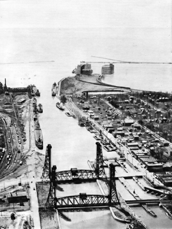
AT PORT COLBORNE, ON LAKE ERIE, is one of the entrances to the Welland Canal, which connects Lakes Erie and Ontario. The canal is nearly twenty-eight miles long, and vessels are raised or lowered 325½ feet in eight locks. The vertical-lift road and rail bridges across the canal are electrically operated and can be opened in one and a half minutes.
London’s Hydraulic Power
For the transmission of power beneath the streets of London there is a network of hydraulic mains, carrying water at a pressure of 700 lb per square inch. This hydraulic power is used for many different purposes, from driving motors to operating lifts and similar mechanisms. It is not generally appreciated that underneath the streets of London, and of many great cities, there are extensive networks of hydraulic power mains similar in their function to the gas and electricity mains, but quite separate from the ordinary water mains.
Triumphs of Canal Building
Photogravure Supplement
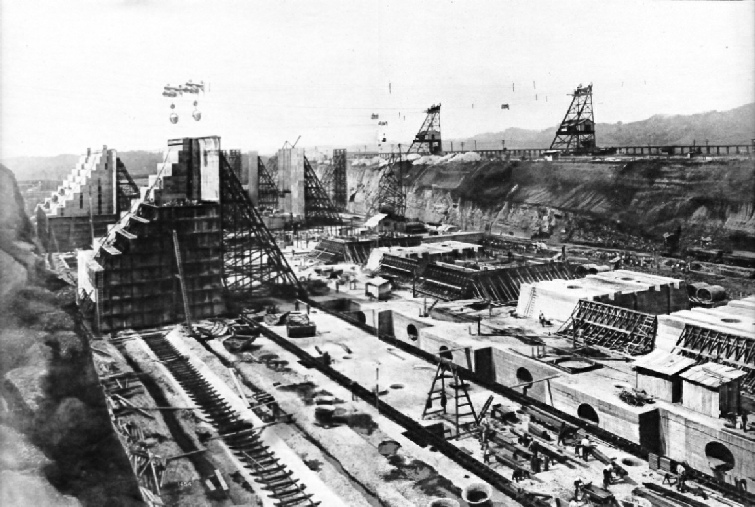
AT MIRAFLORES, near the Pacific entrance to the Panama Canal during its construction. The long approach wall to Miraflores Lock was formed by an earth dam half a mile long. The lock walls are 82 feet high and the two sets of locks lower vessels 55 feet or so according to the state of the tide.
The Sheep Farms of Queensland and New South Wales
ON THE SHEEP FARMS of Queensland and New South Wales water for livestock and for human consumption is obtained by drilling artesian wells to tap the waters of the Great Artesian Basin. The depth of the bores varies and sometimes, as in the well illustrated, pumping is necessary to bring the subterranean water to the surface.
The Rio Grande Dam
RIO GRANDE DAM was completed in 1936. The structure was built by the hydraulic fill process, by which a mixture of earth and water was pumped to form the body to th dam. More than 10,000,000 cubic yards of earth were treated in this way. A concrete core wall was built down to the bedrock.
Artesian Bores in Australia (Part 1)
Underneath the parched lands of Australia lies a great subterranean reservoir, extending below one-fifth of the whole continent. By drilling numerous artesian wells, engineers have brought the waters to the surface in their efforts to combat the menace of drought. This chapter is concluded in part 52.
You can read more about Artesian Wells on this website.
The Corinth Canal
DIVIDING AN ISTHMUS, the Corinth Canal links the Aegean Sea with the Gulf of Corinth and the Ionian Sea. Cut in 1882-93, the canal is absolutely straight for its entire length of 6,937 yards (nearly four miles). It is 25 yards wide at the bottom and 26 feet deep. The cutting has a maximum depth of 260 feet. The canal is crossed by the railway from Athens to Corinth.


The Tower Subway
THE TOWER SUBWAY carries water and hydraulic pressure mains beneath the River Thames. It was built in 1868 as a railway tube by the engineers Barlow and Greathead but proved unsatisfactory as such. It has a diameter of 7 feet. The hydraulic pressure main is on the left.
Triumphs of Canal Building
The name of Brindley is always associated with the building of Great Britain's canal system, which was begun more than 100 years before the great interoceanic waterways such as the Suez and Panama Canals. This chapter deals with one of the most important activities of
the engineer - the cutting of canals. This chapter traces the history of British canals and the part played by engineers such as Brindley and Telford. It describes the cutting of the Suez Canal and of the Panama Canal, and is illustrated by photographs of the work involved in forming many famous canals.
You can read more on Britain’s Canal System, the Corinth Canal, the Suez Canal, the Welland Canal, and the Panama Canal in Shipping Wonders of the World.


Eight-Coupled Locomotive
A STREAMLINED version of the exclusive Cock o’ the North class of the London and North Eastern Railway, No. 2003 Lord President is one of the few eight-wheels-coupled express passenger locomotives at work in Great Britain. These exceptionally powerful engines are of the Mikado, or
2-8-2 type. They were built to haul trains of 500 tons or more on the heavily graded main line between Edinburgh and Aberdeen, which includes both the Forth and the Tay Bridges. On this route, before the advent of the Mikados, double-heading was common.
It is unusual for a modern British express locomotive to have a leading two-wheeled radial truck instead of a leading bogie. Had these locomotives been given bogies, making them 4-8-2s, they would have been unusually long, though not too long for the existing turntables. Other considerations, therefore, influenced the decision to adopt the shorter 2-8-2 wheel arrangement.
Built at the Doncaster Works of the company in 1936, Lord President is generally similar in design to Cock o' the North, which dates from 1934. The most striking difference is that the newer engine is streamlined almost in the same way as the A 4 Pacifics of the LNER.
The engine has three simple cylinders 21-in diameter by 26-in stroke, and piston valves, with a maximum valve travel of 5⅝-in. All three cylinders drive the second coupled axle. The outside cylinders are actuated by Walschaerts valve gear and the inside cylinder by a special form of valve gear devised by Sir Nigel Gresley, designer of the locomotive and Chief Mechanical Engineer of the LNER.
The eight driving wheels are of 6 ft 2-in, the leading wheels of 3 ft 2-in and the trailing wheels of 3 ft 8-in diameter.
The boiler, with a maximum external diameter of 6 ft 5-in, has 121 small tubes, of 2¼-in diameter, and 43 superheater tubes, with a diameter of 5¼-in. The evaporative heating surface is made up: firebox 237, small tubes 1354·2, flue tubes 1122·8 square feet; total 2,714 square feet. To this must be added the 776·5 square feet of the superheater, giving a total heating surface of 3490·5 square feet. The grate area is 50 square feet.
Two Ross “pop” safety valves are fitted; the working pressure is 220 lb per square inch. The tractive effort, at 85 per cent of the boiler pressure, is 43,462 lb, more than that of any other express passenger locomotive so far built in Great Britain, except others of the same class.
The engine weighs 107 tons 3 cwt and the tender 57 tons 18 cwt in working order. Total weight of engine and tender is 165 tons 1 cwt. Of the engine weight no less than 78 tons 19 cwt are available for adhesion.
This is the twenty-fourth article in the series on Modern Engineering Practice.
You can read about the LNER Streamlined Locomotives ion this website.

Concrete Construction
Before moving forms were introduced for concrete work, an average of nine days had to elapse from the time of pouring to the striking of forms. New methods have enabled concrete building to be raised much more quickly. This chapter describes a remarkable method of building concrete structures.
You can read more on Cement and Concrete on this website.
Moving Forms For Concrete Structures
MOVING FORMS were used to build these silos for cement at West Thurrock, Essex. This photograph shows the work at the stage when the walls had reached a height of 20 feet. From the main platforms are hung lower platforms used for finishing the previously poured section. To the left is the concrete hoist, with mixing plant at the foot.


Concrete Building at Highgate
CONCRETE BUILDING erected in 1935 at Highgate, London. Moving forms of a special type were used for pouring the walls of this block of flats. The forms (at the top of the building) were independent of the walls. Thus they could be detached at each floor level to allow the floors to be cast in one piece.
