

© Wonders of World Engineering 2014-


Part 52
Part 52 of Wonders of World Engineering was published on Tuesday 22nd February 1938, price 7d.
Part 52 includes a colour plate showing the two supplementary roller sluices being added to Teddington Weir. The colour plate accompanied the article on Controlling the Thames.
The colour plate also appears as the cover to this Part.
The Cover
The cover of this week’s Part is reproduced as a colour plate. It shows the construction of two new roller sluices in the weir at Teddington, Middlesex. These sluices were built as part of an elaborate improvement scheme put in hand by the Conservators of the River Thames. The scheme and the sluices are described in the chapter entitled “Controlling the Thames” in this week’s Part.

Contents of Part 52
Artesian Bores in Australia (Part 2)
Aqueducts to Manchester
Controlling the Thames
Controlling the Thames (colour plate)
Electric Power from Mercury
Silver Mining
Engineering Models
Mechanical Storage of Power
Refinement and Efficiency (Part 1)
Aqueducts to Manchester
A great part of the water supply for the city of Manchester comes from the Lake District, about a hundred miles away. From Thirlmere and Haweswater, natural lakes enlarged to form reservoirs, the water is carried to Manchester in pipe lines and tunnel aqueducts. Thirlmere supplies about 40,000,000 gallons of water a day and Haweswater is designed to supply no fewer than 75,000,000 gallons a day.
Controlling the Thames
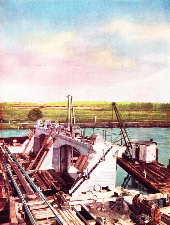
PART OF THE THAMES IMPROVEMENT SCHEME, completed by the Conservators in 1935, was an increase in the weir capacities at Teddingon, Molesey and Sunbury. The colour plate shows the two supplementary roller sluices which were added to Teddington Weir. Before the work could be begun, the entire site had to be enclosed in a cofferdam of sheet steel piling. The foundations, abutments and central pier of the weir were built of mass concrete and the superstructure of reinforced concrete.
The colour plate is also reproduced on the cover of this Part.
Artesian Bores in Australia (Part 2)
Underneath the parched lands of Australia lies a great subterranean reservoir, extending below one-fifth of the whole continent. By drilling numerous artesian wells, engineers have brought the waters to the surface in their efforts to combat the menace of drought. This chapter is concluded from part 51.
You can read more about Artesian Wells on this website.
Bore Sinking in New South Wales
BORE SINKING in New South Wales. When a likely site for an artesian well has been surveyed and selected, engineers establish a camp, all their food and materials having to be transported across rough country. Generally a steam engine provides the power for the drilling.
Controlling the Thames
The River Thames, from its source to Teddington, Middlesex, is controlled by the Thames Conservancy, which is responsible for the maintenance of locks, weirs and other works, as well as for the control of the water level and of navigation. The regulation of river waters is an indispensable activity of the engineer, and the control of the River Thames is of the utmost importance to the people who live on its banks. The river is controlled by a body known as the Conservators of the River Thames, from its source to Teddington. For nearly seventy miles below Teddington the Thames is controlled by the Port of London Authority. The work of the Thames Conservators is described in this chapter. Numerous locks, weirs and artificial channels have been built on the Thames to aid navigation, to regulate the waters and to alleviate flooding.
Silver Mining
Fabulous wealth has been extracted for centuries from the rich and unseemingly unlimited silver mines of South America and Mexico. The comparatively recent discovery of the metal in the United States and in Canada gave rise to modern scientific methods of refining. This chapter describes the silver mines of the world. Most of the world’s silver is mined in America. For centuries before the discovery of America by Westerners, the Aztec and Inca civilizations were mining prolific quantities of silver in countries that are now known as Mexico, Peru, Chile, Bolivia and Colombia. Mexico is still the greatest source of silver. In the last century silver was discovered in the United States and in Canada, and now there are extensive silver mines in those countries.
Mercury-Steam-Electric Power Station
MERCURY-STEAM-ELECTRIC POWER STATION erected by the General Electric Company of America at its works at Schenectady, New York State. Working on the principle devised by an American engineer, W. Le Roy Emmet, this station is unusual in addition because it has been erected out of doors.
Electric Power From Mercury
The problems of converting the heat contained in fuel into useful work with greater economy have led engineers to consider some other fluid than water as a transmitting medium. Mercury is being used in the boilers and turbines in some power stations in the United States. This remarkable new departure in boiler and turbine practice is described in this chapter. In certain power stations in the United States power is generated from boilers using mercury instead of water. Mercury does not begin to vaporize in atmospheric conditions until it has reached a temperature of 675 degrees Fahrenheit. The plant, designed by an American engineer, W. Le Roy Emmet, uses the vapour from the mercury to drive the rotor of a turbine. This new arrangement is still in the early stages of development and so far only three plants have been erected. They are running satisfactorily, however, and are being watched with the greatest interest by engineers, who foresee extensive developments in the future.
Refinement and Efficiency (Part 1)
Unremitting research and far-
Broken Hill Mine, New South Wales
AT BROKEN HILL, in New South Wales, there was discovered in 1883 an outcrop of one of the richest silver-lead-zinc ore deposits in the world. The ore has yielded more than 480,000,000 ounces of silver, but only lead and zinc are now yielded in large quantities. Lead concentrations are sent by rail to Port Pirie, South Australia, for refining.
Representation of the River Mississippi
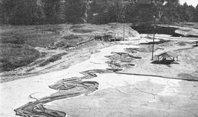
REPRESENTATION OF THE RIVER MISSISSIPPI, showing, in the foreground, the Yazoo River area, in the United States Waterways Experiment Station at Vicksburg, Mississippi. The model of the river represents a total length of ninety-


DRILLS for boring the twenty-nine miles of tunnel aqueduct which will form part of the pipe line designed to carry the water from Haweswater to Manchester. Haweswater is being dammed by a concrete structure 95 feet high and about a quarter of a mile long. Water from reservoirs in neighbouring valleys is being brought to Haweswater by tunnels and the final supply to Manchester will be carried through twenty-nine miles of tunnels, twelve and a half miles of covered channels and seven siphons
UNLINED TUNNELS are used for the Haweswater and Thirlmere aqueducts, except where the nature of the rock demands a lining of concrete or brick. When the waters of Thirlmere had been raised 25 feet by the building of a masonry dam across its natural outlet, the area of the lake was increased from 330 acres to 830 acres, giving a capacity of 8,256 million gallons. The aqueduct which conveys these waters to Manchester is ninety-six miles long.
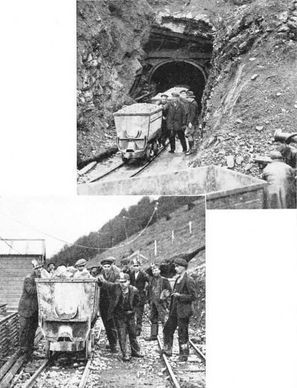
A TUNNEL PORTAL on the route from Haweswater. Spoil from the workings is removed in wagons running on rails laid as the excavation proceeds. Before each blasting operation twenty-eight holes were drilled 7 feet into the working face. Sometimes as many as 250 steel bits were required for boring the drill-holes necessary for one blast. The Haweswater aqueduct follows a straighter and more direct route to Manchester than the Thirlmere aqueduct, of which the tunnel sections are 7 feet high and 7 feet wide. Water takes about two days to cover the distance from the Lake District to Manchester. All the work was put in hand by the Manchester Corporation Waterworks.
ON THE HAWESWATER SCHEME work has been in progress for some years. In addition to the building of the dam across the valley below the lake, many other engineering works have to be undertaken before the £10,000,000 scheme is completed. Some of the men wear flashlamps in their caps after the fashion of miners. The elevation of the water level at Haweswater involves also the diversion and rebuilding of a motor road. Buildings submerged in the new reservoir have to be replaced.

Controlling the Thames
EXTENSIVE FLOODS sometimes occur in winter months when the River Thames overflows its banks. This photograph was taken near Sonning, Berkshire, in March 1937. The Conservators are continually undertaking engineering works to minimize the risks of flood.
TO REDUCE THE FLOODS two roller sluices, each 35 feet wide, were added to Teddington Weir, the lowest weir on the Thames, as part of a large improvement scheme completed in 1935.


Engineering Models
The effects of large-scale engineering schemes, such as harbour works, hydro-electric plant or river control, can be studied beforehand by the use of scale models, of which some remarkable examples have been made. In almost every branch of engineering scale models are extensively used for experimental and testing purposes. Models of ships, for instance, are generally built before the expensive constructional work is begun; they are tested in tanks such as that at the National Physical Laboratory, Teddington, Middlesex. Civil engineers, too, use scale models extensively. Before extensive dock and harbour works are carried out large models are often built on which the effects of wind, current and tide can be studied. One of the largest models of this kind was built in London to represent the Port of Rangoon, Burma, and its approaches. The model measured 45 feet by 40 feet and represented an area of about 50 miles square. An ingenious arrangement of plungers simulated the effects of the tide and the variation between spring tide and neap tide was reproduced by epicyclic gearing. Some ten thousand gallons of water were used daily when the model was operating normally. One of the most extensive models is that at Vicksburg, Mississippi. Here there is a faithful reproduction in miniature of parts of the Mississippi River. Experiments are continually in progress to determine, for instance, the effects of erosion and the best means of preventing it. The Rangoon, Vicksburg, and similar models are described in this chapter.
You can read about How the Modern Ship is Tested in Shipping Wonders of the World.
Mechanical Storage of Power
When hydro-electric power was installed to drive the machinery of two mills on the banks of the River Tweed in Peeblesshire, an ingenious system was devised to store up power while the mills were not working. A remarkable arrangement of hydroelectric power has been installed at Walkerbum, where two mills were for many years operated by the power of waterwheels. In 1918 it was decided to replace the two waterwheels with a single hydro-electric power plant, using low-pressure turbines. The power developed would be used normally only during working hours. For the rest of the time the water power would be running to waste had not the engineers devised an ingenious alternative. The solution was to use the power not required for operating the mills to pump water into a reservoir, thus accumulating a reserve water supply.

Reinforced Concrete Reservoir Being Built
REINFORCED CONCRETE RESERVOIR being built 1,000 feet above the power station to take water pumped up by the turbines when electric current is not required for driving the mill machinery. The reservoir is in the form of a huge box some 192 feet square and 15 ft 6 in deep. The side walls taper in thickness from 21 inches at the base to 8 inches at the top. The rate of taper is not uniform.

The Drop-
THE DROP-